


WELDING GENERATOR BRUSH AND COMMUTATOR INSPECTION AND
SERVICE (continued)
PROCEDURE (continued)
Pitted and Arc Damaged Commutator:
If pitting and arc damage to the commutator is evident,
the machine may have been used with badly worn
brushes. The brush spring tension may have been too
low, or the brushes may have been sticking in the hold-
ers. An out-of-adjustment rocker or a serious overload
may also cause this condition.
• Examine the inside of the brush covers and other
parts that are close to the commutator. If there is
a significant amount of solder and debris that has
been thrown from the commutator, the armature
will need to be replaced and the stator coils must
be carefully examined and tested for damage.
• Perform the Weld Circuit Ground and Short
Circuit Test.
• If the brushes are worn out, replace them and re-
surface or clean the commutator as needed. If re-
cutting is required, the minimum diameter of the
commutator is 6.895 in. If the brush springs
appear weak, discolored or damaged in any way,
replace them as well. The brush holder plates and
retainers should be clean, smooth, and undam-
aged so the brushes can move freely as they wear.
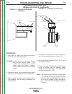
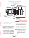
• Check the rocker position. Be certain that it is
aligned with or very close to the factory drill mark.
See Figure F.16. IMPORTANT: If the rocker posi-
tion requires adjustment, do not over tighten the
rocker clamping screw. This screw should be tight-
ened to a torque of 70 to 75 Inch-Lbs. Over tight-
ening can destroy the rocker.
Uneven Commutator appearance:
If the commutator appears to have some normal col-
ored bars and some blackened bars, the armature may
be shorted.
• If excessive sparking is observed and/or the weld
output is abnormal, the armature should be
replaced.
• If the commutator has uneven color, but there is no
sign of serious generator performance problems,
the commutator may only need to be cleaned by
lightly stoning the surface. See caution note on
commutator stone usage.
Examine the brushes:
The brushes and springs should all be in place and not
be excessively worn. Brushes should be replaced if
they are worn to within ¼” of the pigtail lead.
The pigtail lead of each brush should be positioned so
it allows free movement of the brush while it wears.
The brushes should be seated so that the face of each
brush makes 95% minimum contact with the commuta-
tor. Lightly stone the commutator to seat the brushes.
See caution note on commutator stone usage.
Examine the brush holders:
The brush holder insulators must be clean and in good
condition and all of the hardware must be in place. See
Figure F.16. Replace any insulators that are cracked
or damaged in any way.
When installing the brush holders, they should be rotat-
ed toward the brush retainer (clockwise rotation when
facing the brush holder mounting screw.) until they
stop. The edge of the brush holder plate should be par-
allel with the surface of the commutator and positioned
.030 to .090 from the surface of the commutator. The
brush holder mounting screw should be tightened to a
torque of 24 to 28 Ft Lbs.
The brush holder plate and retainer assembly must be
clean and smooth; nothing should prevent free move-
ment of the brushes. All electrical connections to the
brush holders must be clean, and tight. The recom-
mended torque for 5/16-18 brush holder connection
screws is 8 Ft.-Lbs.
TROUBLESHOOTING AND REPAIR
F-46 F-46
SAE-400 SEVERE DUTY
Return to Section TOC Return to Section TOC Return to Section TOC Return to Section TOC
Return to Master TOC Return to Master TOC Return to Master TOC Return to Master TOC