


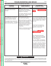

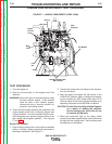
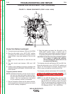
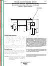
Idler
Solenoid
Spring
Idler Rod
Speed
Control
Lever
Ball
Joint
Lock
Nut
Pulley
Fan Blades
Possible Strobe-Tach
Mark Points
FIGURE F.1 – ENGINE COMPONENTS (CODE 10856)
ENGINE RPM ADJUSTMENT TEST (continued)
TEST PROCEDURE
1. Turn the engine off
2. Open the left side door, on the engine end of the
machine.
WARNING: Secure the door in the open position using
the door restraint system. If the machine
does not have a door restraint system,
remove the door or securely restrain it to
prevent it from falling closed.
3. Check that the linkage attaching the solenoid to the
engine speed control lever is properly aligned and
in good condition. It is more important that the sole-
noid linkage be more precisely aligned when in the
high speed (de-energized position). See Figures
F.1 and F. 2.
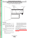
Strobe-Tach Method:
1. Place a highly visible mark on the engine crankshaft
pulley, or another rotating component connected to
the engine crankshaft. See Figure F.1.
2. Connect the strobe-tach according to the manufac-
turer’s instructions.
3. Start the engine and place the idle switch in the
“HIGH IDLE” position. Apply a resistive load operat-
ing the machine at 100% output (400 amps @ 36
volts) for about 30 minutes to get the machine up to
operating temperature and the RPM to stabilize.
CAUTION: Do Not Short the Output Studs Together
as a means of loading the machine.
Serious damage can result that will not
be covered by Warranty.
4. Direct the strobe-tach light on the highly visible
mark that had been applied earlier and synchronize
the light with the rotating mark. See the strobe-tach
manufacturer’s instructions.
TROUBLESHOOTING AND REPAIR
F-22 F-22
SAE-400 SEVERE DUTY
Return to Section TOC Return to Section TOC Return to Section TOC Return to Section TOC
Return to Master TOC Return to Master TOC Return to Master TOC Return to Master TOC