


THEORY OF OPERATION
E-2 E-2
SAE-400 SEVERE DUTY
Return to Section TOC Return to Section TOC Return to Section TOC Return to Section TOC
Return to Master TOC Return to Master TOC Return to Master TOC Return to Master TOC
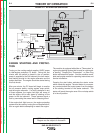
ENGINE STARTING AND PROTEC-
TION
Turning on the run/stop switch supplies 12VDC power
to idler/engine protection PC board. During the first
minute after the switch is placed in the on position,
power is supplied to the Fuel solenoid, the hour meter,
and flashing circuits for the engine alternator and the
exciter alternator. The engine should be started during
this first minute.
After one minute, the PC board will begin to monitor
the oil pressure switch, cooling system temp switch,
and the engine alternator. If a fault is detected in any
of these systems, the engine fault light will come on
and the engine will be shut down by shutting off the
power to the fuel solenoid. These systems signal a
fault by connecting the sense lead to chassis ground.
If the engine fault light turns on, the engine protection
system must be reset by turning the run/stop switch off,
then on again before attempting to restart the engine.
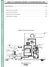
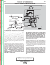
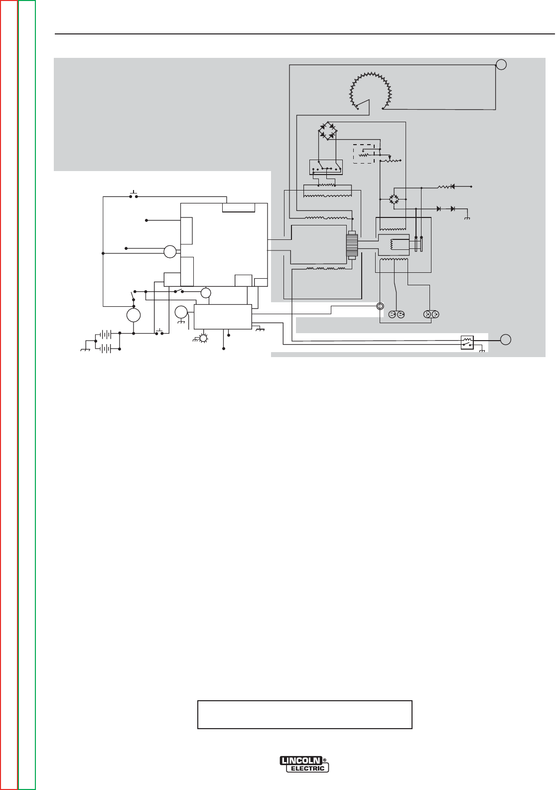
FIGURE E.2 - ALTERNATOR OPERATION
The machine is equipped with either a “Thermostart” or
a glow plug starting system that is used for cold weath-
er starting. Pressing the “Thermostart” or Glow Plug
button activates this system. See the machine name-
plate and engine manual for operating instructions and
service information.
Pressing the start button activates the starter motor
which cranks the engine. The start button is a momen-
tary contact switch that routes power from the battery
to the starting terminal of the starter solenoid. The
starter will crank the engine even if the run/stop switch
is in the off position.
---
DIESEL
ENGINE
THERMOSTAT
INJECTION
PUMP
SOLENOID
SYSTEM
THERMOSTART
BUTTON
IDLE SWITCH
IDLE
SOLENOID
IDLE / ENGINE
PROTECTION BOARD
TO IDLE / ENGINE
PROTECTION BOARD
RUN/STOP
SWITCH
S
T
A
R
T
E
R
TO IDLE/ENGINE
PROT. BOARD
OIL
PRESSURE
SWITCH
TEMP
SWITCH
STARTER
SOLENOID
AMMETER
START
BUTTON
ENGINE
FAULT
LIGHT
HOUR
METER
TO
FLASHING
RESISTOR
AND
DIODE
INTERPOLE COILS
GENERATOR
ARMATURE
SERIES COILS
SHUNT COILS
115 VAC
RECEPTACLES
230 VAC
RECEPTACLES
AUXILIARY
POWER
WINDINGS
EXCITER
WINDING
EXCITER
ROTOR
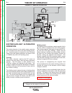
MIN
(OFF)
MAX
OUTPUT
CONTROL
ELECTRODE
TERMINAL
RESISTOR
POLARITY
SWITCH
REMOTE
RHEOSTAT
LOCAL
RHEOSTAT
(JOB SELECTOR)
TO HOUR METER
FLASHING
RESISTOR AND
DIODE
(+)
(+)
(-)
(-)
AC
AC
(-) (+)
WORK
TERMINAL
TO ALTERNATOR
FLASH/SENSE
TO INJECTION
PUMP SOLENOID
NOTE: Unshaded areas of Block Logic
Diagram are the subject of discussion