


THEORY OF OPERATION
E-8 E-8
SAE-400 SEVERE DUTY
Return to Section TOC Return to Section TOC Return to Section TOC Return to Section TOC
Return to Master TOC Return to Master TOC Return to Master TOC Return to Master TOC
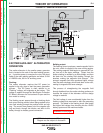
WELDING GENERATOR OPERA-
TION (Continued)
Current Control:
The Current Control handle turns a rotor inside the
reactor assembly. This reactor assembly functions
together with the generator’s series coils to regulate
the output current and produce the drooping volt/amp
curve that is so important to a constant current welding
source. This current control has almost no effect on
the OCV.
Series coils and reactor:
Current from two of the four sets of brushes is routed
through the generator’s series coils and the reactor
assembly before being connected to one of the weld
output terminals. These series coils are wound and
arranged in such a way as to reduce or buck the cur-
rent flowing from the armature. Because the series
coils do not reduce the weld output until current is flow-
ing, OCV is not reduced, and starting the arc is easier.
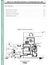
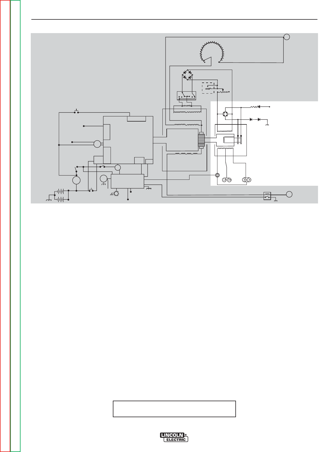
FIGURE E.2 - GENERAL DESCRIPTION
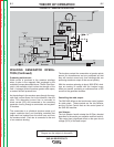
Reactor Assembly:
The reactor assembly functions like a specialized, high
current rheostat, and is connected in parallel with the
series coils of the generator. At the very minimum set-
ting the reactor is electrically open, forcing all of the
current flowing from the armature to pass through the
series coils. This setting will produce the lowest weld
current that can be set with this control.
Moving the current control off of the minimum setting
closes the circuit in the reactor and allows some of the
current to bypass the series coils. Continuing to move
the control to the higher settings reduces the resis-
tance of the reactor and causes even more current to
bypass the series coils. When the current control is set
to maximum, the reactor resistance is at minimum, and
nearly all of the current passes through the reactor.
Because the current passing through the reactor is not
reduced by the bucking action of the series coils, weld
current is increased.
DIESEL
ENGINE
THERMOSTAT
INJECTION
PUMP
SOLENOID
SYSTEM
THERMOSTART
BUTTON
IDLE SWITCH
IDLE
SOLENOID
IDLE / ENGINE
PROTECTION BOARD
TO IDLE / ENGINE
PROTECTION BOARD
RUN/STOP
SWITCH
S
T
A
R
T
E
R
TO IDLE/ENGINE
PROT. BOARD
OIL
PRESSURE
SWITCH
TEMP
SWITCH
STARTER
SOLENOID
AMMETER
START
BUTTON
ENGINE
FAULT
LIGHT
HOUR
METER
TO
FLASHING
RESISTOR
AND
DIODE
INTERPOLE COILS
GENERATOR
ARMATURE
SERIES COILS
SHUNT COILS
115 VAC
RECEPTACLES
230 VAC
RECEPTACLES
AUXILIARY
POWER
WINDINGS
EXCITER
WINDING
EXCITER
ROTOR
MIN
(OFF)
MAX
OUTPUT
CONTROL
ELECTRODE
TERMINAL
RESISTOR
POLARITY
SWITCH
REMOTE
RHEOSTAT
LOCAL
RHEOSTAT
(JOB SELECTOR)
TO HOUR METER
FLASHING
RESISTOR AND
DIODE
(+)
(+)
(-)
(-)
AC
AC
(-) (+)
WORK
TERMINAL
TO ALTERNATOR
FLASH/SENSE
TO INJECTION
PUMP SOLENOID
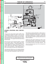
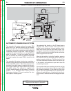
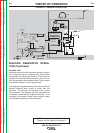
NOTE: Unshaded areas of Block Logic
Diagram are the subject of discussion