


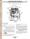
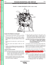
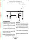
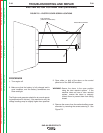
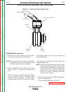

EXCITER COVER
FIVE SCREWS
(TWO ON OTHER SIDE)
FIGURE F.3 – EXCITER COVER SCREW LOCATIONS
BRUSH AND SLIP RING SERVICE PROCEDURE
(Exciter / Auxiliary Power Alternator) (continued)
PROCEDURE
1. Open either, or both of the doors on the control
panel end of the SAE-400 machine.
WARNING: Secure the doors in the open position
using the door restraint system. If the
machine does not have a door restraint
system, remove the doors or securely
restrain them to prevent them from falling
closed.
2. Remove the covers from the exciter / auxiliary
power alternator by removing the screws securing
it. See Figure F.3.
3. Examine brushes, slip rings, and brush holder.
• Brushes should be clean and free from oil or
grease.
• The brushes should be of sufficient length and
have adequate spring tension.
• Brushes should be making good, continuous
contact with the slip rings, and should be riding
near the center of the slip rings. (The brush
holder bracket may need to be slightly bent to
achieve acceptable alignment.)
(Generally, the brushes should be replaced if either
brush has less than 1/4” remaining before it reach-
es the end of its travel.)
4. If the slip rings are very dark in color, display evi-
dence of excessive arcing, or have worn prema-
turely, these may be signs of a grounded or shorted
rotor. Perform the Exciter Rotor Resistance and
Ground Test.
TROUBLESHOOTING AND REPAIR
F-26 F-26
SAE-400 SEVERE DUTY
Return to Section TOC Return to Section TOC Return to Section TOC Return to Section TOC
Return to Master TOC Return to Master TOC Return to Master TOC Return to Master TOC