


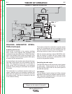


OUTPUT PROBLEMS
Observe Safety Guidelines detailed in the beginning of this manual.
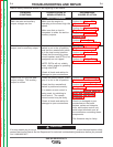
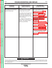
PROBLEMS
(SYMPTOMS)
POSSIBLE AREAS OF
MISADJUSTMENT(S)
RECOMMENDED
COURSE OF ACTION
If for any reason you do not understand the test procedures or are unable to perform the tests/repairs safely,
contact the Lincoln Electric Service Department for technical troubleshooting assistance before you proceed.
Call 1-888-935-3877.
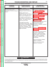
CAUTION
Both the weld and auxiliary
output voltages are low
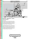
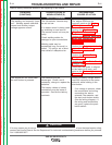
There is no, or very low weld
output, and no auxiliary output.
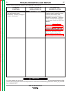
There is no, or very low weld
output voltage. The auxiliary
output is normal.
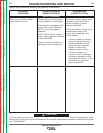
Make sure the engine is
operating at the correct high idle
speed.
Make sure that no load is
connected to either the weld or
auxiliary outputs.
Check that the electrode polarity
switch is not in the off position,
and that the remote/local switch
is in the local control position.
Check that the auxiliary power
circuit breakers and GFCIs (if so
equipped) are not tripped.
NOTE: GFCIs will not reliably
reset, unless engine is operating
at high idle RPM.
Check all leads and cables for
damaged or poor connections.
Check the polarity switch; make
sure it is not in the off position.
Check that the remote/local
switch is positioned correctly.
If a remote current control is
being used, try switching to
local control. The remote
current control may be faulty.
Check all leads and cables for
damaged or poor connections.
Perform the Engine RPM
Adjustment Test.
Perform the Brush and Slip
Ring Service Procedure.
Perform the Exciter Rotor
Voltage Test.
Perform Exciter Rotor
Resistance and Ground Test.
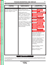
Perform the Brush and Slip
Ring Service Procedure.
Perform the Exciter Rotor
Voltage Test.
Perform the Exciter Rotor
Resistance and Ground Test.
Perform the Shunt Field Coil
Resistance and Ground Test.
Perform the Shunt Field Circuit
Voltage Test.
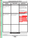
Perform the Welding Generator
Brush and Commutator
Inspection and Service
Procedure.
Check for damaged or poor
connections at the brush
holders, series and interpole
coils, weld output control unit,
weld output terminals, and all
the conductors connecting these
components.
The Armature may be faulty.
TROUBLESHOOTING AND REPAIR
F-4 F-4
SAE-400 SEVERE DUTY
Return to Section TOC Return to Section TOC Return to Section TOC Return to Section TOC
Return to Master TOC Return to Master TOC Return to Master TOC Return to Master TOC