


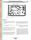

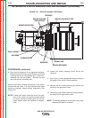

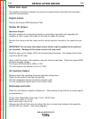
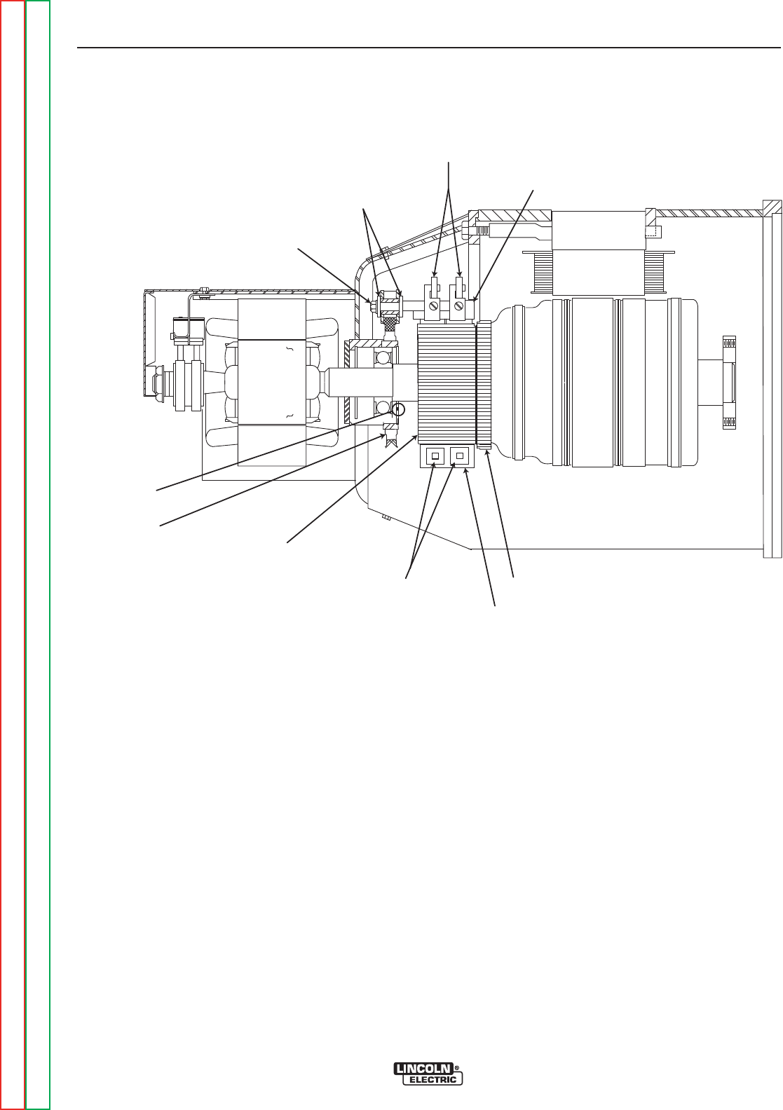
ARMATURE
COMMUTATOR
SPRINGS
BRUSH HOLDER PLATE
BRUSHES
BRUSH RETAINER
BRUSH HOLDER
INSULATORS
MOUNTING SCREW
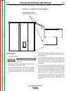
DRILL MARK
ROCKER
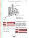
FIGURE F.31 – ROCKER & MARK LOCATIONS
ALTERNATOR STATOR REMOVAL AND REPLACEMENT (continued)
PROCEDURE (continued)
9. Drain the fuel and store it in an approved container.
Disconnect the fuel line from the bottom of the tank
and plug the line to avoid getting dirt or other cont-
aminants into the fuel system. Remove the fuel
tank and the tank mounting rails.
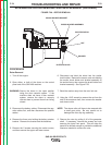
Note the drill spots marking the position of the exciter
bracket and the rocker. It is very important that these
marks be precisely aligned during reassembly. See
Figure F.31
NOTE: If these drill marks cannot be found, the posi-
tions of the rocker and exciter bracket should
be clearly marked so these parts can be pre-
cisely aligned when the machine is reassem-
bled.
10. Loosen the rocker clamping screw, but do not
remove it.
11. Use a hoist, or other appropriate means to support
the weight of the exciter frame assembly.
12. Remove the four screws securing the exciter end
bracket to the generator frame.
13. Carefully pry the exciter stator/end bracket assem-
bly away from the generator frame.
NOTE: The welding generator brush holder and rocker
assembly will also be removed.
TROUBLESHOOTING AND REPAIR
F-83 F-83
SAE-400 SEVERE DUTY
Return to Section TOC Return to Section TOC Return to Section TOC Return to Section TOC
Return to Master TOC Return to Master TOC Return to Master TOC Return to Master TOC