


ENGINE FUEL SYSTEM VOLTAGE TESTS (continued)
PROCEDURE
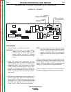
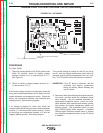
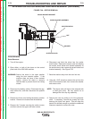
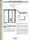
For Codes 11199 and 11408
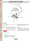
1. Place the run/stop switch in the “RUN” position and
within 30 seconds, check for 11 to 13 VDC
between terminal J31-9 (+) and terminal B-1 (-).
2. Check for battery voltage between terminal J31-1
(+) and terminal B-1 (-).
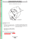
3. Check for positive battery voltage between the ter-
minal where lead 212F connects to the engine tem-
perature switch and a good chassis ground. See
the wiring diagram.
If the correct voltage is present for tests #1 and #2,
check the wiring and connections between the PC
board, the primary solenoid, and the fuel pump. See
wiring diagram.
If no voltage is present for tests #1 and #2, check the
run/stop switch and all wiring and connections between
terminal J31-1 and the positive battery terminal. Check
all the wiring and connections between Terminal B-1
and the negative battery terminal. See wiring diagram.
If the correct voltage is not present for test #3, check
the wiring between the engine temperature switch and
run/stop switch.
If the correct voltage is present for test #2, but not for
test #1, and the voltage reading was taken within 30
seconds of placing the run/stop switch in the “run” posi-
tion, The PC board is faulty and should be replaced.
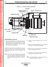
NOTE: The fuel solenoids, temperature switch and the
fuel pump are part of the Perkins engine and
should be tested and, if necessary, repaired or
replaced by a qualified Perkins engine techni-
cian. To help in precisely identifying a fuel sys-
tem failure, approximate solenoid resistance
values and current draw for the fuel pump are
included on the machine schematic.
TROUBLESHOOTING AND REPAIR
F-76 F-76
SAE-400 SEVERE DUTY
Return to Section TOC Return to Section TOC Return to Section TOC Return to Section TOC
Return to Master TOC Return to Master TOC Return to Master TOC Return to Master TOC