


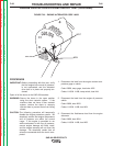

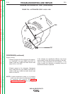

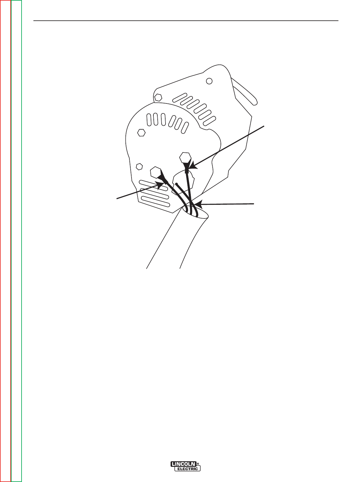
#237
#224
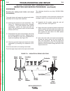
GROUND
FIGURE F.25 – ALTERNATOR CODE 10856
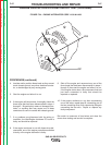
ENGINE ALTERNATOR TEST (continued)
PROCEDURE
1. Open the right side cover, on the radiator end of the
SAE-400 machine.
WARNING: Secure the door in the open position using
the door restraint system. If the machine
does not have a door restraint system,
remove the door(s) or securely restrain
them to prevent them from falling closed.
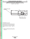
2. Locate the engine alternator (See Figure F.25 &
Figure F.26)
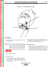
3. Check voltage as follows:
4. Run/stop switch off:
• Chassis ground to the B+ terminal of the alterna-
tor, (Lead #237 for code 10856) (Lead #51 for
codes 11199 and 11408) the meter should read
battery voltage.
• Chassis ground to the alternator flash/sense lead,
(Lead #224 for cod 10856) (Lead #59 for codes 11199
and 11408) the meter should read 0 volts.
Run/stop switch on:
• Chassis ground to the flash/sense lead, (Lead
#224 for cod 10856) (Lead #59 for codes 11199
and 11408) the meter should read 11.5 to 12.9
Volts DC during first 30 seconds of operation.
(This time may be 60 seconds on some models.)
TROUBLESHOOTING AND REPAIR
F-70 F-70
SAE-400 SEVERE DUTY
Return to Section TOC Return to Section TOC Return to Section TOC Return to Section TOC
Return to Master TOC Return to Master TOC Return to Master TOC Return to Master TOC