


THEORY OF OPERATION
E-3 E-3
SAE-400 SEVERE DUTY
Return to Section TOC Return to Section TOC Return to Section TOC Return to Section TOC
Return to Master TOC Return to Master TOC Return to Master TOC Return to Master TOC
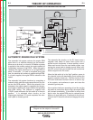
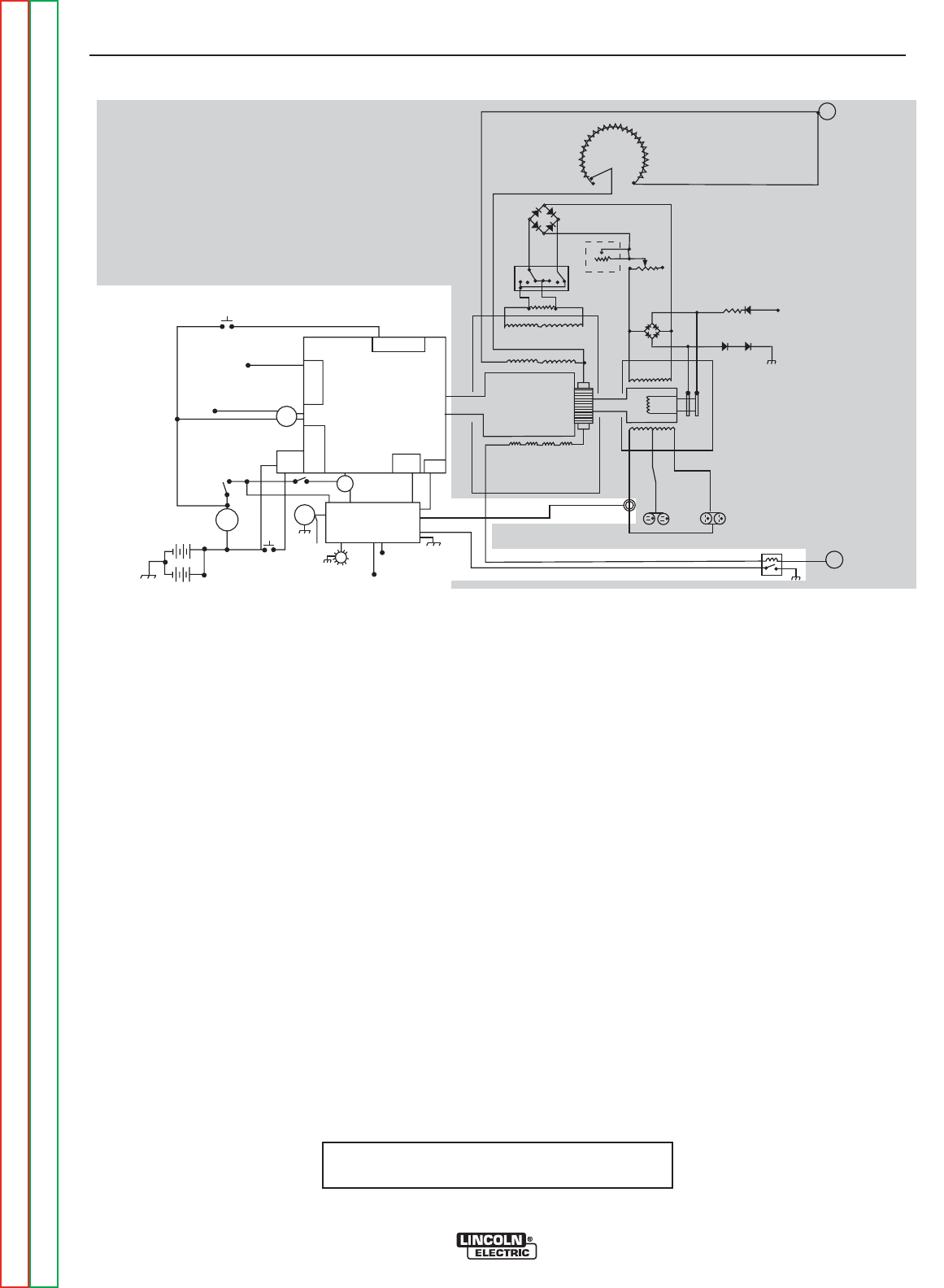
AUTOMATIC ENGINE IDLE SYSTEM
The automatic idle system reduces the engine RPM
when there is no electrical demand on the machine.
When an arc is struck, or a load of 100 Watts or greater
is applied to the auxiliary output, the engine speed will
immediately increase to high RPM. When the load is
released, the engine continues to run at high RPM for
about 12 seconds. If a load is re-applied during this
time, the machine will continue to operate at high RPM.
If no load is applied, the engine RPM is reduced to idle
speed.
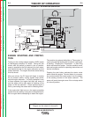
The automatic idle system functions by energizing a
solenoid, which pulls the engine speed control to a pre-
set low idle RPM position. When this solenoid is de-
energized, the engine speed is controlled by the gov-
ernor which maintains the engine RPM at the specified
high RPM setting. The solenoid is supplied with
+12VDC power whenever the idle switch is in the auto
position. It is activated when circuitry on the
Idler/engine shutdown PC board completes the sole-
noid’s path to chassis ground.
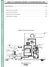
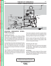
FIGURE E.2 - ENGINE STARTING AND PROTECTION
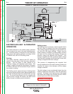
The automatic idle circuitry on the PC board uses a
magnetic reed switch to sense weld current and a
toroidal current transformer to sense auxiliary current.
When weld current flows the reed switch closes, con-
necting the sense lead to chassis ground. When suffi-
cient AC current flows, the toroidal current transformer
sends a signal to the PC board.
When the idle switch is in the “high” position, power to
the solenoid is shut off deactivating it and causing the
engine to operate at high rpm. The idle circuitry on the
PC board continues to sense if there is a load on any
of the outputs, and continues to open and close the
solenoid’s ground path.
If the machine had been operating at low idle and the
idle switch is moved from auto to high, the engine RPM
will increase immediately. If the switch is moved from
high to auto, the engine RPM may be reduced imme-
diately or it could take up to 12 seconds for the idle cir-
cuitry on the PC board to activate and engage the sole-
noid.
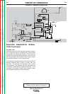
NOTE: Unshaded areas of Block Logic
Diagram are the subject of discussion
---
DIESEL
ENGINE
THERMOSTAT
INJECTION
PUMP
SOLENOID
SYSTEM
THERMOSTART
BUTTON
IDLE SWITCH
IDLE
SOLENOID
IDLE / ENGINE
PROTECTION BOARD
TO IDLE / ENGINE
PROTECTION BOARD
RUN/STOP
SWITCH
S
T
A
R
T
E
R
TO IDLE/ENGINE
PROT. BOARD
OIL
PRESSURE
SWITCH
TEMP
SWITCH
STARTER
SOLENOID
AMMETER
START
BUTTON
ENGINE
FAULT
LIGHT
HOUR
METER
TO
FLASHING
RESISTOR
AND
DIODE
INTERPOLE COILS
GENERATOR
ARMATURE
SERIES COILS
SHUNT COILS
115 VAC
RECEPTACLES
230 VAC
RECEPTACLES
AUXILIARY
POWER
WINDINGS
EXCITER
WINDING
EXCITER
ROTOR
MIN
(OFF)
MAX
OUTPUT
CONTROL
ELECTRODE
TERMINAL
RESISTOR
POLARITY
SWITCH
REMOTE
RHEOSTAT
LOCAL
RHEOSTAT
(JOB SELECTOR)
TO HOUR METER
FLASHING
RESISTOR AND
DIODE
(+)
(+)
(-)
(-)
AC
AC
(-) (+)
WORK
TERMINAL
TO ALTERNATOR
FLASH/SENSE
TO INJECTION
PUMP SOLENOID