


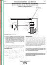
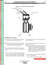

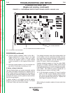
POSITIVE
SLIP RING
NEGATIVE
SLIP RING
BRUSH HOLDER ASSEMBL
Y
OHMMETER LEADS
BRUSHES
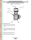
FIGURE F.9 – SLIP RING LOCATIONS
EXCITER ROTOR RESISTANCE AND GROUND TEST
(Exciter / Auxiliary Power Alternator) (continued)
PROCEDURE (continued)
5. Using the ohmmeter, check the rotor winding resis-
tance across the slip rings. Normal resistance is
approximately 41.5* ohms, at 77°F. (25° C.) See
Figure F.9.
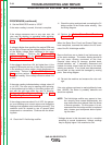
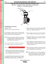
6. Measure the resistance to ground. Place one meter
probe on either of the slip rings. Place the other
probe on any good, unpainted chassis ground. The
resistance should be very high, at least 500,000
(500k) ohms.
If the resistance measurements are not as specified
the rotor may be faulty and should be replaced.
If these resistance values are normal, continue testing,
using the dynamic rotor resistance and ground test.
TROUBLESHOOTING AND REPAIR
F-35 F-35
SAE-400 SEVERE DUTY
Return to Section TOC Return to Section TOC Return to Section TOC Return to Section TOC
Return to Master TOC Return to Master TOC Return to Master TOC Return to Master TOC