


OPERATION
B-5 B-5
SAE-400 SEVERE DUTY
Return to Section TOC Return to Section TOC Return to Section TOC Return to Section TOC
Return to Master TOC Return to Master TOC Return to Master TOC Return to Master TOC
WELDER CONTROLS
POLARITY SWITCH
Turn the Arc Polarity switch to electrode positive or
electrode negative as required for each particular
application.
CONTROL OF WELDING CURRENT
Purpose of Controls
The continuous “Current Control” is the main current
adjuster. The “Job Selector” is both a fine current
adjuster and the continuous Open Circuit Voltage
adjuster. Open Circuit Voltage (OCV) controls the arc
characteristics.
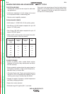
“Job Selector”
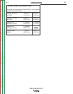
The “Job Selector” dial is divided into four colored sec-
tions providing OCV ranges as follows:
Color Title OCV Range
White Large Electrodes High OCV
Black Normal Welding Medium OCV
Red Overhead & Vertical Low OCV
Grey Special Applications Extra-Low OCV
The “Job Selector” is usually set in the black range
because it provides a soft “Buttering “ arc desired for
most welding. Some operators prefer to set the “Job
Selector” in the red range for a snappy “Digging” arc
when welding vertical up or overhead.
“Current Control”
Do not adjust the “Current Control” while welding
because this can damage the control.
------------------------------------------------------------------------
The “Current Control” dial is calibrated in amperes on
three
separate colored dials corresponding to the
white, black and red ranges of the “Job Selector” dial.
For example: when the “Job Selector” is set on the
black range, the approximate welding current is indi-
cated on the black scale of the “Current Control” dial.
HowtoSettheControls
Assume you want a normal soft arc and about 135
amps, using a 5/32” (4.0 mm) electrode:
1. Set the “Job Selector” at the center of the black
range.
2. Set the “Current Control” to read 135 amps on the
black dial.
3. Start to weld.
4. If you want a little more current, turn the “Job
Selector” up (counterclockwise) to increase cur-
rent. If you want a little less current, turn the “Job
Selector” down (clockwise) to decrease current.
5. If dialing the desired current with the “Job
Selector” moves the setting outside the black
range causing undesirable arc characteristics, turn
the “Job Selector” back to the center of the black
range. Then turn the “Current Control” up or down
a little as needed. Readjust the “Job Selector” for
the exact characteristics and current desired.
REMOTE CONTROL
A receptacle and “Local/Remote” control switch on the
lower front control panel and a remote control box with
100 ft. (30.5 m) of cord for adjusting the OCV at the
welding site are standard. Putting the switch in the
“REMOTE” position allows fine current control at the
remote control box while placing the switch in the
“LOCAL” position allows fine current control at the “Job
Selector” on the machine.
AUXILIARY POWER CONTROLS
Note: GFCI receptacles are an option and if installed,
see the “MAINTENANCE SECTION” for detailed
information on testing and resetting the GFCI
receptacle.
115 VAC Receptacle
One 20 amp, 115 VAC duplex receptacle provides 115
VAC for auxiliary power. A total of 26 amps can be
drawn from this receptacle.
230 VAC Receptacle
One 15 amp, 230 VAC duplex receptacle provides 230
VAC for auxiliary power. A total of 13 amps can be
drawn from this receptacle.
Circuit Breakers
The circuit breakers provide separate overload current
protection for each half of the 115 V duplex receptacle.
The circuit breakers provide overload current protec-
tion in both current carrying wires of the 230 V duplex
receptacle.
Ground Stud
Provides a connection point for connecting the
machine to earth ground. For the safest grounding pro-
cedure refer to “Machine Grounding” in the INSTAL-
LATION section of this manual.
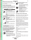
CAUTION