


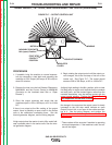

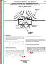
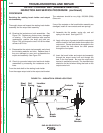

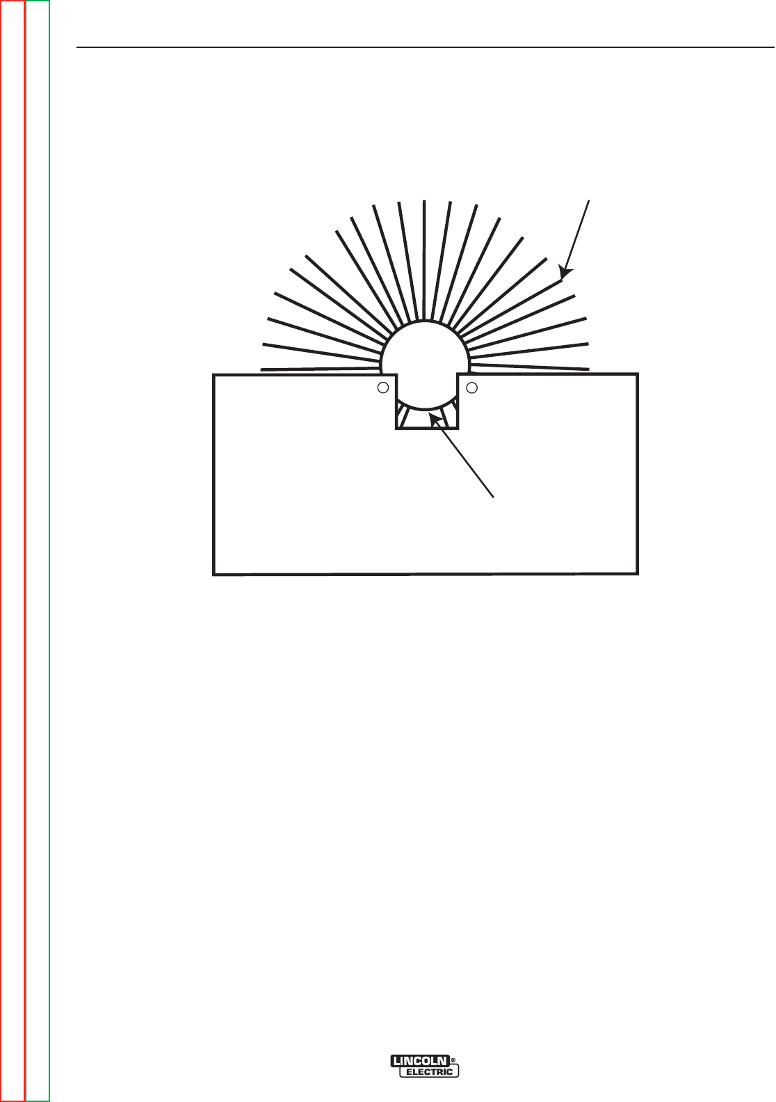
WINDING
INSULATED
WEDGE
FIGURE F.20 – BRUSH & SPRING
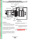
OUTPUT CONTROL UNIT (VARIABLE REACTOR)
INSPECTION AND SERVICE PROCEDURE (continued)
PROCEDURE (continued)
Servicing the continuous control unit:
8. Clean the continuous output control unit by using
low pressure air to remove any excess dust and dirt.
If the unit is greasy or oily, a more thorough clean-
ing will be required. The unit must be clean and
completely dry before continuing.
9. Ground test the unit by testing the resistance
between the following points:
• Chassis ground to winding
• Chassis ground to the insulated steel wedge (at
the bottom of continuous output control inside
diameter)
• Insulated steel wedge to the winding. See Figure
F.20 .
The resistance should be very high, 500,000 (500k)
Ohms min.
If the resistance is too low, disconnect the remaining
connection cable and look for any connection with
chassis ground, including any buildup of conductive dirt
contacting the winding. Repeat the above resistance
tests. If the low resistance is determined to be within
the continuous output control unit, it will need to be
replaced.
Use very fine, 400 to 600 grit sand paper or a cylinder
hone to clean away any dirt, oxidation, or minor arc pit-
ting from the output control bore.
TROUBLESHOOTING AND REPAIR
F-61 F-61
SAE-400 SEVERE DUTY
Return to Section TOC Return to Section TOC Return to Section TOC Return to Section TOC
Return to Master TOC Return to Master TOC Return to Master TOC Return to Master TOC