


RETEST AFTER REPAIR
F-89 F-89
SAE-400 SEVERE DUTY
Return to Section TOC Return to Section TOC Return to Section TOC Return to Section TOC
Return to Master TOC Return to Master TOC Return to Master TOC Return to Master TOC
Retest after repair
The machine should be retested if any parts are replaced that could affect the machine’s
electrical characteristics.
Engine output:
Perform the Engine RPM Adjustment Test
Welder DC Output:
Maximum Output:
Bring the machine to normal temperature by connecting a load bank and operating the
machine at 100% output (400 amps @ 36 volts) for about 30 minutes.
Remove the load and set the output control and job selector rheostat to the maximum posi-
tion.
IMPORTANT: Do not move the output control while a load is applied to the weld out-
put terminals. Damage to the output control unit may result.
Read the open circuit voltage (OCV) at the weld output terminals. The voltage should mea-
sure 93 to 99 DC Volts.
Apply a 500 Amp load to the machine using the resistive load bank. Check the engine RPM
and weld terminal voltage.
The Engine RPM should be 1680 to 1795
The weld output volts should be 45 to 51 VDC.
AC Auxiliary Output:
Machine should be operating at normal operating temperature.
Place the idle switch in the high idle position.
230 Volt receptacles should read 240 to 254 AC volts.
115 Volt receptacles should read 118 to 128 AC Volts.
Field amps and volts:
Place the Job Selector rheostat to Maximum. (The machine should still be at normal operat-
ing temperature.)
Exciter volts, Measured at slip rings: 124 to 132 DC Volts
Exciter rotor amps: 2.1 to 2.6
Shunt field amps: 2.55 to 3.2
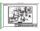
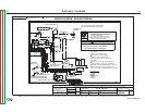
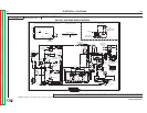
(Measure the Shunt Field current at either the blue or brown wires between the generator
and the 500 ohm resistor. See wiring diagram.)