


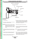


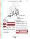

GENERATOR FRAME REMOVAL AND REPLACEMENT (continued)
PROCEDURE
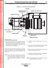
Remove the generator frame
1. Turn off Engine.
2. Perform the Alternator Rotor Removal
Procedure.
3. Perform the Alternator Stator Removal
Procedure.
4. Disconnect all of the wires and cables that connect
to the stator/frame assembly. Carefully mark them
for reassembly.
5. Remove the mounting bolts from the generator feet.
6. Using a hoist and sling, very carefully lift the gener-
ator only enough so the generator frame will clear
the welder frame and can be removed. The sling
should be positioned near the center of the genera-
tor frame.
Carefully watch the clearance between the engine and
any other components while hoisting, especially the
clearance between the engine fan, the fan shroud, and
radiator. Loosen or remove the radiator if necessary.
7. Support the engine at the generator adapter plate
end.
8. With the generator frame still supported by the
sling, (Be certain the sling is positioned at the cen-
ter of gravity of the generator frame.) and the weight
of the engine resting on the supports that were
placed in the previous step, remove the screws
securing the generator frame to the engine adapter
plate.
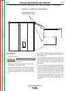
9. Carefully pry and wiggle the generator frame to free
it from the adapter plate, and then slide the genera-
tor frame off of the armature. Adjust the height of
the stator frame as needed to assure that it can
slide off the armature without damage to any of the
armature or stator windings.
Replacing the Generator Frame
1. During reassembly, anti-seize compound should be
applied to the screw threads.
2. Carefully inspect the mating surfaces of the engine
adapter plate and the generator frame. The mating
surfaces must be clean and undamaged.
3. Lift the generator frame with the rope sling and very
carefully slide it over the armature. Be very careful
that the armature and stator windings are not dam-
aged.
4. Align the bolt holes and install the screws that had
been removed earlier. Carefully and evenly tighten
them, making sure that the mating surfaces come
together cleanly all the way around. Tighten the
screws; see the torque specification page for cor-
rect torque values.
5. Remove the supports from the engine and carefully
lower the generator frame. Install the rubber
mounts.
6. Reverse the removal procedure to reassemble the
machine. Be sure to secure all cables, and wires.
Replace all cable ties that had been removed dur-
ing disassembly.
7. Perform the Alternator Stator Replacement
Procedure.
8. Perform the Alternator Rotor Replacement
Procedure.
TROUBLESHOOTING AND REPAIR
F-86 F-86
SAE-400 SEVERE DUTY
Return to Section TOC Return to Section TOC Return to Section TOC Return to Section TOC
Return to Master TOC Return to Master TOC Return to Master TOC Return to Master TOC