


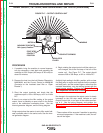

SHUNT FIELD COIL RESISTANCE AND GROUND TEST (continued)
PROCEDURE
1. Turn the engine off.
2. Open both of the doors on the control panel end of
the SAE-400 machine. The roof may also need to
be removed on some models.
WARNING: Secure the doors in the open position
using the door restraint system. If the
machine does not have a door restraint
system, remove the doors or securely
restrain them to prevent them from falling
closed.
Shunt Coil Resistance Test:
3. Place the polarity switch in the “OFF” position.
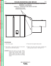
Locate the 500 Ohm/50 Watt resistor located on the
back of the control panel, just below the 115 VAC
duplex receptacle. Leave all of the leads connect-
ed to the resister, and measure the resistance
across it.
The resistance should measure approximately
36.5* ohms at 77°F. (25° C.)
If the resistance reading is correct, proceed to the
Shunt coil ground test.
• If the resistance reading is slightly high, about 40*
Ohms, The 500 Ohm resistor may be open.
• If the resistance is significantly higher than 40*
Ohms, check the wiring between the test points
and the shunt coils. Check the lead connecting
the two shunt coils together inside the generator
frame. See the wiring diagram and the internal
generator diagram. If these wires and connec-
tions are undamaged, one of the coils is likely
open. Replace the shunt field coil set.
• If the resistance is significantly lower than 36.5*
Ohms at 77°F. (25° C.), check the wiring between
the test points and the coils for damaged insula-
tion, pinched wires, etc. If the wires and insula-
tion are in good condition, disconnect at least one
of the shunt coil wires from the resistor and test
the resistance of just the shunt coil set. See the
wiring diagram and internal generator diagram. If
the resistance is still significantly lower than 40
Ohms, one of the coils is likely shorted. Replace
the shunt coil set.
Shunt Coil Ground Test:
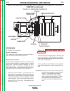
4. Place the polarity switch in the “OFF” position.
Locate the 500 Ohm resistor located on the back of
the control panel, just below the 115 VAC duplex
receptacle. Leave all of the leads connected to the
resistor, and measure the resistance between either
of the resistor terminals and a good clean chassis
ground. The resistance should be very high,
500,000 (500k) Ohms minimum.
• If the resistance is too low, disconnect the shunt
coil leads from the resistor and position them so
they cannot make electrical contact with any-
thing. See the wiring diagram. Test the resis-
tance between either of the shunt coil lead wires
and a good, clean chassis ground.
• If the resistance is still lower than 500,000 (500k)
Ohms, check the shunt coil leads between the
test points and the coils. Also check the lead
connecting the two shunt coils together inside of
the generator. Look for pinched wires and dam-
aged insulation. If the low resistance is deter-
mined to be between chassis ground and one of
the shunt coils, replace the coil set.
• If the coil set tests normal when disconnected,
check the resistor and polarity switch for low
resistance to chassis ground. Repair or replace
these parts as needed.
5. Reconnect the wires and replace any covers that
have been removed.
*NOTE: The resistance of the copper windings will
change with temperature. Higher tempera-
tures will produce slightly higher resistance,
and lower temperatures will produce slightly
lower resistance.
TROUBLESHOOTING AND REPAIR
F-50 F-50
SAE-400 SEVERE DUTY
Return to Section TOC Return to Section TOC Return to Section TOC Return to Section TOC
Return to Master TOC Return to Master TOC Return to Master TOC Return to Master TOC