


THEORY OF OPERATION
E-6 E-6
SAE-400 SEVERE DUTY
Return to Section TOC Return to Section TOC Return to Section TOC Return to Section TOC
Return to Master TOC Return to Master TOC Return to Master TOC Return to Master TOC
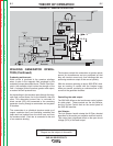
WELDING GENERATOR OPERA-
TION
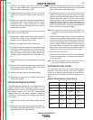
Overview:
The welding generator is coupled directly to the engine
and produces the DC current required for welding and
arc gouging. The welding power is induced in the wind-
ings of the armature when it spins in a magnetic field.
The power produced in the armature is converted to
direct current (DC) by a commutator and a set of car-
bon brushes, which are then connected to the interpole
coils, the series coils, and the reactor assembly. The
weld current is controlled by varying the field (Job
Selector) and the reactor (Current Control) setting,
using the front panel control knobs.
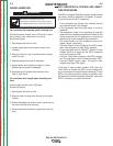
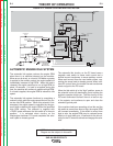
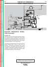
Excitation and field control:
Before any welding current can be produced, there
must be a magnetic field in which the armature can
spin. Creating this magnetic field is often described as
exciting the generator, and is accomplished by passing
controlled DC current through two shunt coils in the
generator stator.
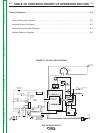
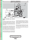
FIGURE E.2 - GENERAL DESCRIPTION
The power used to excite the generator starts out as
AC current produced by the exciter/auxiliary alternator.
This AC current passes through a remote/local switch
and then through either a remote or the front panel
mounted 64 Ohm rheostat. The now controlled AC
current is then converted to direct current (DC) by a full
wave bridge rectifier. The DC output from the rectifier
then passes through a polarity reversing switch, and is
then applied to the two series connected shunt coils in
the generator stator.
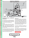
Reversing the polarity of the field also reverses the
polarity of the weld current. When the polarity switch is
moved to the neutral position, the shunt coils are dis-
connected. The resulting collapse of the magnetic field
around these coils can produce a very high induced
voltage. A 500 Ohm resistor is connected in parallel
with the shunt coil set to reduce this voltage to a level
that is within the limits of the insulation used. It also
helps reduce arcing and damage to the polarity switch.
DIESEL
ENGINE
THERMOSTAT
INJECTION
PUMP
SOLENOID
SYSTEM
THERMOSTART
BUTTON
IDLE SWITCH
IDLE
SOLENOID
IDLE / ENGINE
PROTECTION BOARD
TO IDLE / ENGINE
PROTECTION BOARD
RUN/STOP
SWITCH
S
T
A
R
T
E
R
TO IDLE/ENGINE
PROT. BOARD
OIL
PRESSURE
SWITCH
TEMP
SWITCH
STARTER
SOLENOID
AMMETER
START
BUTTON
ENGINE
FAULT
LIGHT
HOUR
METER
TO
FLASHING
RESISTOR
AND
DIODE
INTERPOLE COILS
GENERATOR
ARMATURE
SERIES COILS
SHUNT COILS
115 VAC
RECEPTACLES
230 VAC
RECEPTACLES
AUXILIARY
POWER
WINDINGS
EXCITER
WINDING
EXCITER
ROTOR
MIN
(OFF)
MAX
OUTPUT
CONTROL
ELECTRODE
TERMINAL
RESISTOR
POLARITY
SWITCH
REMOTE
RHEOSTAT
LOCAL
RHEOSTAT
(JOB SELECTOR)
TO HOUR METER
FLASHING
RESISTOR AND
DIODE
(+)
(+)
(-)
(-)
AC
AC
(-) (+)
WORK
TERMINAL
TO ALTERNATOR
FLASH/SENSE
TO INJECTION
PUMP SOLENOID
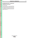
NOTE: Unshaded areas of Block Logic
Diagram are the subject of discussion