


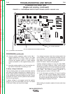

WELD CIRCUIT GROUND AND SHORT CIRCUIT TEST (continued)
PROCEDURE
1. Turn the engine off.
Weld circuit ground test:
1. Rotate the output control to the minimum output
position.
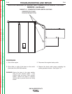
2. Measure the resistance between either of the two
weld output terminals and a clean chassis ground
connection.
3. The resistance measurement should be very high
500,000 (500k) Ohms minimum.
If the resistance is lower than 500k Ohms:
4. Move the output control away from the minimum
position and recheck the resistance. If the resis-
tance is now 500k Ohms or greater; check for a
damaged or missing insulator bushing at the output
control unit.
5. If the resistance is still less than 500k Ohms,
Remove the welding generator brushes, or pull
them away from the commutator and isolate them
so they cannot come in contact with anything
except the brush holder where they are attached.
6. Check the resistance between chassis ground and
each output terminal, and between chassis ground
and the commutator.
If the commutator has low resistance to chassis
ground, the armature is defective.
7. If the resistance measured at the “WORK” terminal
is low, carefully examine the interpole coils, and the
heavy leads, and the brush holders connected to
the interpole coils. Check for damaged, dirty or
missing brush holder insulators. Check for a dam-
aged or dirty weld output “WORK” terminal.
8. If the resistance measured at the “ELECTRODE”
terminal is low, examine the output control unit, the
series coils, and the heavy leads and brush holders
connected to them. Check for damaged, dirty or
missing brush holder insulators. Check for a dam-
aged or dirty weld output “ELECTRODE” terminal.
If necessary, disconnect the output control unit and
test it separately. See the Output Control Unit
(Variable Reactor) Inspection and Service
Procedure.
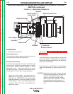
9. Test for a short circuit condition between the elec-
trode and work circuits.
10. With the brushes still isolated as described above,
check the resistance between the two weld termi-
nals. The resistance should be very high, 500,000
(500k) Ohms minimum.
11. If the resistance measurement is too low, check
the heavy weld current carrying leads and connec-
tions for damaged insulation or dirt buildup
between the electrode (Series Coils) and work
(Interople Coils) circuits. If the low resistance point
is between the stator coils, the coils will require
replacement or repair.
TROUBLESHOOTING AND REPAIR
F-48 F-48
SAE-400 SEVERE DUTY
Return to Section TOC Return to Section TOC Return to Section TOC Return to Section TOC
Return to Master TOC Return to Master TOC Return to Master TOC Return to Master TOC