


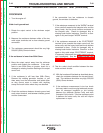
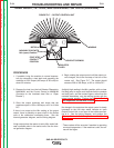
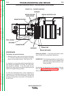
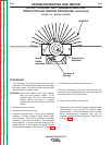

ARMATURE
COMMUTATOR
SPRINGS
BRUSH HOLDER PLATE
BRUSHES
BRUSH RETAINER
BRUSH HOLDER
INSULATORS
MOUNTING SCREW
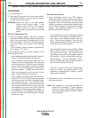
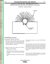
DRILL MARK
ROCKER
FIGURE F.18 – ROCKER W/MARKS
ROCKER ADJUSTMENT PROCEDURE (continued)
PROCEDURE
The factory set point drill marks:
1. When the rocker is set for the first time at the facto-
ry, a 1/8” drill is used to mark the position of both the
rocker and the exciter bracket. See Figure F.18
If a machine is not operating within the specified limits,
and nothing else appears to be faulty, the rocker posi-
tion should be checked. If the drill marks are not
aligned, the rocker and/or the exciter bracket should be
reset to the original factory position.
If it has been determined that a rocker adjustment is
necessary on an unaltered machine; the rocker should
only be moved in very small increments, and the total
movement should be no more than ½ the diameter of
the drill mark.
Setting the Rocker - if the factory drill mark is miss-
ing or invalid due to component replacement.
IMPORTANT: The following procedures should only be
attempted if all the other systems have
been thoroughly checked and are func-
tioning normally.
A tachometer will be required for this phase of the test.
See the Engine RPM Adjustment Test for details
about measuring engine RPM.
TROUBLESHOOTING AND REPAIR
F-56 F-56
SAE-400 SEVERE DUTY
Return to Section TOC Return to Section TOC Return to Section TOC Return to Section TOC
Return to Master TOC Return to Master TOC Return to Master TOC Return to Master TOC