


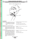

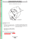

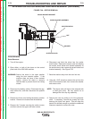
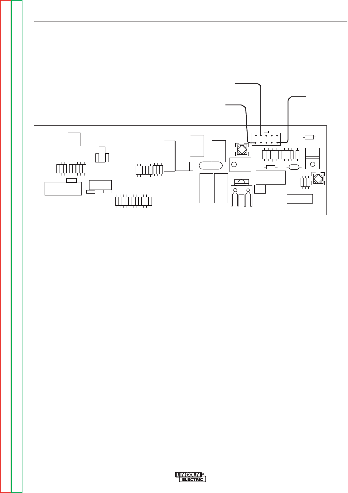
J1-5 (-), CHASSIS
GROUND
J1-9 (+), 11 TO 13 VOLTS
TO FUEL SOLENOIDS
J1-1 (+), BATTERY
VOLTAGE INPUT TO
PC BOARD
FIGURE F.27 – PC BOARD
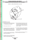
ENGINE FUEL SYSTEM VOLTAGE TESTS (continued)
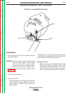
PROCEDURE
1. Open the doors on the SAE-400 machine.
WARNING: Secure the doors in the open position
using the door restraint system. If the
machine does not have a door restraint
system, remove the doors or securely
restrain them to prevent them from falling
closed.
2. Check the wiring and connections on the
Idle/Engine protection PC board, the engine fuel
system injection pump solenoids, the fuel system
temperature switch, (The fuel pump for Codes
11199 & 11408), and chassis ground. Look for dirty,
corroded, or damaged terminals, including the
Molex terminals connecting the wiring to the PC
board. Look for poor crimp connections and dam-
aged wiring.
3. Make sure the batteries are in good condition, and
are fully charged, then place the run/stop switch in
the run position. Within 30 seconds, check for bat-
tery voltage (11 to 13 VDC), across the primary and
secondary fuel solenoids, (and the fuel pump for
Codes 11199 & 11408). See the wiring diagram.
NOTE: The secondary solenoid will only have voltage
if the fuel system temperature switch is closed.
Consult a Perkins engine service facility for
precise information about the temperature
switch and other fuel system electrical compo-
nents.
If battery voltage is present at the solenoids and the
fuel pump (If equipped), and the starter motor is crank-
ing the engine normally, the problem is likely in the
engine. Engine problems should be diagnosed and
repaired by a qualified Perkins engine technician.
If battery voltage is not present at the solenoids and
fuel pump (if equipped) follow the procedures below.
TROUBLESHOOTING AND REPAIR
F-74 F-74
SAE-400 SEVERE DUTY
Return to Section TOC Return to Section TOC Return to Section TOC Return to Section TOC
Return to Master TOC Return to Master TOC Return to Master TOC Return to Master TOC