


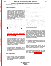


ROCKER ADJUSTMENT PROCEDURE (continued)
PROCEDURE (continued)
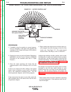
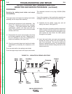
Initial rocker placement:
1. The rocker should be initially positioned so the
center of brushes visually lines up with the
center of the main poles. Lining up the four
brush holder studs with the four exciter brack-
et mounting bolts is acceptable for initial place-
ment. The rocker should be tight against the
shoulder of the hub and the clamping screw
should be tightened only enough to assure the
rocker cannot move.
IMPORTANT: DO NOT OVER TIGHTEN. Over
tightening the rocker clamp screw
can destroy the rocker.
2. Check that the brush holders are properly
installed and positioned correctly. See the
Welding generator Brush and Commutator
Inspection and Service Procedure.
3. Start the engine, place the idle switch in the
high idle position, and seat the brushes using
a commutator stone. See the Welding gener-
ator Brush and Commutator Inspection and
Service Procedure.
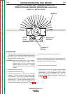
4. Use a load bank to apply a 100% duty cycle
load (400 amps @ 36 volts). Look at the
brushes while the load is applied. If excessive
sparking is observed, adjust the rocker position
to minimize sparking. Generally, moving the
rocker slightly in the direction of the armature
rotation will reduce sparking.
5. Continue running the machine under load for
at least 30 minutes to bring the machine up to
normal operating temperature and to fully seat
the brushes.
Check for Max output.
6. Remove the load, set the output control and
rheostat to maximum, re-apply the load and
adjust the load bank
to apply a 500 Amp load
to the machine.
WARNING: Do not move the Current Control while
the machine is under load.
7. |Measure the output voltage, it should read
between 45 and 51 Volts DC
8. Measure the engine RPM, it should measure
between 1680 and 1795 RPM.
If the engine RPM is not within specification,
Perform the Engine RPM Adjustment Test, if the
engine high idle RPM is normal, but the load RPM
is significantly less than specified above, the
engine or governor may be malfunctioning. See
the engine troubleshooting procedures in this man-
ual and/or have the engine serviced or repaired by
a qualified engine technician.
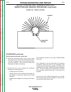
If the weld output voltage is lower than specified
above, the rocker position will need to be adjusted.
Generally, moving the rocker opposite the arma-
ture rotation direction will increase output voltage.
When making this adjustment, the rocker should
only be moved in very small increments. The
adjustment may need to be repeated several times
to achieve the desired result.
9. Remove the load and check the voltage at the
output studs (OCV). The voltage should mea-
sure 93 to 99 Volts DC.
After the rocker has been adjusted and the
machine is operating normally, the rocker locking
screw should be tightened to 70-75 Inch-Lbs.
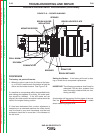
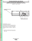
If new parts had been installed, the new rocker
and/or exciter bracket location should be marked
with a 1/8” drill mark. See Figure F.18.
TROUBLESHOOTING AND REPAIR
F-57 F-57
SAE-400 SEVERE DUTY
Return to Section TOC Return to Section TOC Return to Section TOC Return to Section TOC
Return to Master TOC Return to Master TOC Return to Master TOC Return to Master TOC