


OPERATION
B-4 B-4
SAE-400 SEVERE DUTY
Return to Section TOC Return to Section TOC Return to Section TOC Return to Section TOC
Return to Master TOC Return to Master TOC Return to Master TOC Return to Master TOC
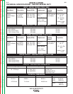
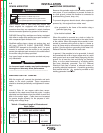
ENGINE CONTROLS
IGNITION SWITCH
When placed in the “ON” position, this switch ener-
gizes the fuel solenoid. When placed in the “OFF” posi-
tion, the flow of fuel to the injection pump is stopped to
shut down the engine.
“IDLER” SWITCH
The idler switch has two positions, “HIGH” and
“AUTO”.
When in “HIGH” ( ) position, the engine will run
continuously at high idle.
When in “AUTO” ( / ) idle position, the idler
operates as follows:
a. Welding
When the electrode touches the work, the welding
arc is initiated and the engine accelerates to full
speed.
After welding ceases (and no auxiliary power is
being drawn), the engine will return to low idle after
approximately 10 to 14 seconds.
b. Auxiliary Power
With the engine running at low idle and auxiliary
power for lights or tools is drawn (approximately
100-150 watts or greater) from the receptacles, the
engine will accelerate to high speed. If no power is
being drawn from the receptacles ( and not weld-
ing) for 10-14 seconds, the idler reduces the engine
speed to low idle.
ENGINE TEMPERATURE GAUGE
Displays the coolant temperature in the engine block.
ENGINE OIL PRESSURE GAUGE
Displays the oil pressure to the engine. When the
engine starts running, watch for the oil pressure to
build up. If no pressure shows within 30 seconds, stop
the engine and consult the engine instruction manual.
BATTERY CHARGING AMMETER
Displays the current going from the charging alternator
into the batteries. It is normal for charging current to be
high (above 15 amps) after starting or when the batter-
ies are ‘low’ on charge.
ENGINE HOUR METER
The engine hour meter records the total running time
on the engine in hours. It can be used to keep a record
of maintenance on the engine and or welder.
ENGINE PROTECTION SYSTEM
The engine protection system shuts down the engine
under high coolant temperature, low engine oil pres-
sure, broken belt or alternator failure conditions by
allowing the fuel solenoid valve to close.
AIR INTAKE SHUT-OFF
Code 10856:
This code uses an air intake shut-off device that is
manually engaged and blocks all intake air from enter-
ing the engine.
To shut down the engine, simply pull the emergency
stop handle on the lower control panel.
This air intake shut-off device must be reset manually
inside of the welder.
• Place the Ignition toggle switch in the “off” position.
• Manually turn the air intake shut-off reset handle such
that the handle is in-line with the air intake hoses. The
air intake shut-off is located on the top of the engine
between the muffler and the air filter.
Codes 11199 and 11408:
These codes have an automatic/manual device that
blocks all intake air from entering the engine.
The automatic feature of this shut-off device will
engage should excessive over speeding occur. The
valve is calibrated at the factory to shutdown before
damage occurs to the engine or generator.
To manually shut down the engine, simply pull the
emergency stop handle on the lower control panel.
This air intake shut-off device will reset automatically,
generally within one minute.
IMPORTANT: Before restarting engine, verify that the
air intake shut-off is in the open position. DO NOT
ATTEMPT TO START ENGINE WITH THE AIR
INTAKE SHUT-OFF IN THE CLOSED POSITION.
This may cause severe damage to the engine.
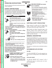
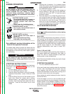
WARNING
•
Muffler and Engine may be hot!