


EXCITER STATOR SHORT CIRCUIT & GROUND TEST (continued)
PROCEDURE
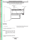
1. Open either, or both of the doors on the control
panel end of the SAE-400 machine.
WARNING: Secure the doors in the open position
using the door restraint system. If the
machine does not have a door restraint
system, remove the doors or securely
restrain them to prevent them from falling
closed.
2. Make sure that nothing is plugged into the auxiliary
receptacles.
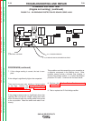
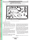
3. Disconnect and isolate the ground lead connected
to the neutral side of the 115 VAC auxiliary recepta-
cle. See the wiring diagram.
4. Disconnect and isolate the exciter winding leads.
(Leads 4 and 5 for code 10856, leads 203A and
602C for codes 11199 and 11408.) See the wiring
diagram.
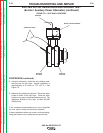
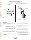
5. Using an ohmmeter; check the resistance between
the following points. Resistance should read very
high, 500,000 (500k) ohms minimum.
• From chassis ground and one of the exciter wind-
ing leads.
• From chassis ground and one of the neutral termi-
nals of the 115 VAC receptacle. (The neutral ter-
minal is the larger of the two slots).
• From one of the neutral terminals of the 115 VAC
receptacle to one of the exciter leads.
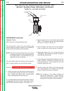
If any of these readings are less than 500,000 (500k)
ohms, be certain that the windings are completely dry
and check for grounded components or wiring that
remain connected to the stator, such as circuit break-
ers, receptacles, etc. See wiring diagram. If neces-
sary, disconnect and isolate the stator leads as close to
the stator winding as possible.
If the low resistance to ground, or between individual
stator windings is determined to be within the stator,
the stator is defective and should be replaced.
TROUBLESHOOTING AND REPAIR
F-42 F-42
SAE-400 SEVERE DUTY
Return to Section TOC Return to Section TOC Return to Section TOC Return to Section TOC
Return to Master TOC Return to Master TOC Return to Master TOC Return to Master TOC