


#59
#51
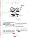
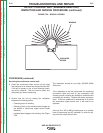
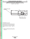
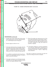
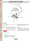
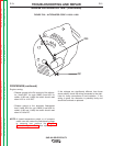
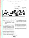
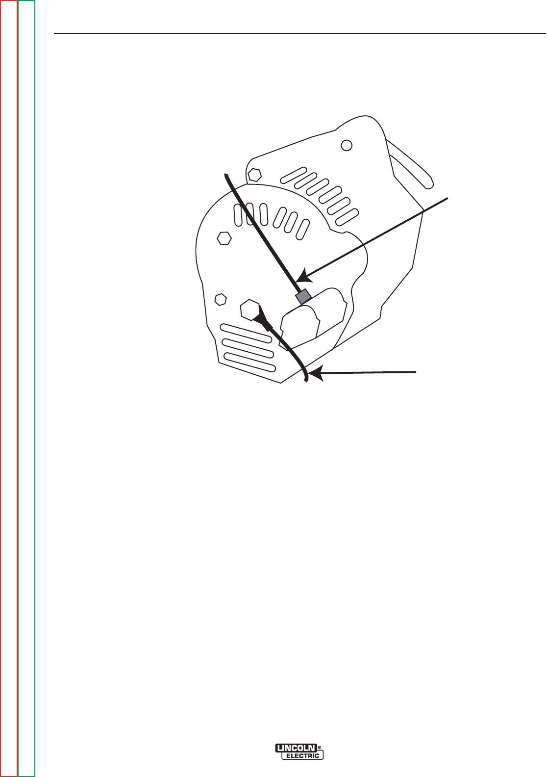
FIGURE F.24 – ENGINE ALTERNATOR CODE 11199 &11408
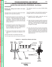
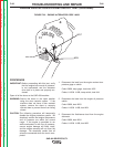
ENGINE PROTECTION SYSTEM CIRCUIT TEST (continued)
PROCEDURE (continued)
4. Insulate and/or position these leads so they cannot
touch chassis ground, any other electrical conduc-
tor, or be damaged by any moving parts.
5. Start the engine and allow it to run.
6. If the engine still shuts down, thoroughly check the
three wires that had been disconnected in steps 1
through 3. Be particularly aware of damaged insu-
lation, or anything that may cause one of these
conductors to come in contact with chassis ground.
7. If no problems are discovered with the wiring or
insulation, the Idler/Engine shutdown PC board is
faulty and should be replaced.
8. If the engine continues to run with these wires dis-
connected, one of the engine protections switches
is faulty or the engine alternator is faulty.
9. Shut off the engine and reconnect any one of the
three leads that had been disconnected in steps 1
through 3, then start the engine and allow it to run.
If the engine shuts down, the component that had
just been connected is faulty and should be
repaired or replaced.
10. If the engine continues to run after reconnecting
one of the wires, repeat step #9, connecting one of
the two remaining wires, then repeat step #9 again
connecting the last wire. Repair or replace any
faulty component.
Be certain to reconnect all lead wires and close the
doors when testing and service is complete.
TROUBLESHOOTING AND REPAIR
F-67 F-67
SAE-400 SEVERE DUTY
Return to Section TOC Return to Section TOC Return to Section TOC Return to Section TOC
Return to Master TOC Return to Master TOC Return to Master TOC Return to Master TOC