


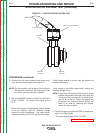
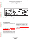
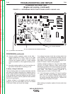

J1-1
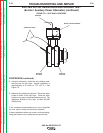
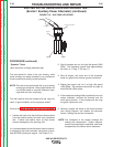
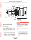
(+) BATTERY VOLTAGE
J1-10, FLASHING AND HOUR METER OUTPUT
J1-5, CHASSIS GROUND
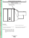
FIGURE F.13 – IDLER/ENGINE PROTECTION PC BOARD CODES 10856
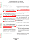
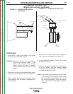
FLASHING VOLTAGE TEST
(Engine not running) (continued)
PROCEDURE (continued)
7. If this voltage reading is correct, the test is com-
plete.
If the voltage is significantly higher than expected:
There may be an open rotor winding or faulty brushes
or slip rings. Perform the Brush and Slip Ring
Service Procedure, and the Exciter Rotor
Resistance and Ground Test.
If the voltage measures zero or significantly lower than
specified (Be sure that the voltage reading was taken
within 30 seconds after the run/stop switch was moved
to the run position. Reset the switch and retest if nec-
essary.)
This condition could be caused by a poor connection or
a defective component in the flashing circuit. Other
possible causes include a shorted rotor winding, a
shorted field bridge rectifier, or a failed Idler/Engine
protection PC board. Continue with the tests below.
8. Perform the Exciter Rotor Resistance and
Ground Test.
9. Test or replace the D1 field bridge rectifier.
TROUBLESHOOTING AND REPAIR
F-39 F-39
SAE-400 SEVERE DUTY
Return to Section TOC Return to Section TOC Return to Section TOC Return to Section TOC
Return to Master TOC Return to Master TOC Return to Master TOC Return to Master TOC