


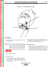

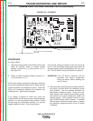
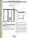
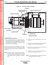


EXCITER ROTOR
BRUSH HOLDER ASSEMBLY
NUT
WASHER
SLEEVE COLLAR
BRUSH HOLDER BRACKET
FIGURE F.29 – ROTOR REMOVAL
ALTERNATOR ROTOR REMOVAL AND REPLACEMENT (continued)
PROCEDURE
Rotor Removal
1. Turn off the engine.
2. Open either, or both of the doors on the control
panel end of the SAE-400 machine.
WARNING: Secure the doors in the open position
using the door restraint system. If the
machine does not have a door restraint
system, remove the doors or securely
restrain them to prevent them from falling
closed.
3. Disconnect the battery cables. Disconnect the neg-
ative cables first, and then disconnect the positive
cables.
4. Remove the three nuts holding the battery retainer
bracket. Remove the bracket and the batteries.
5. Remove the 5 screws securing the exciter covers,
and then remove the upper and lower covers.
6. Disconnect and label the wires from the exciter
brush holder. Remove the screws, and nuts holding
the exciter brush holder and bracket assembly to
the exciter frame, then remove the brush holder and
bracket assembly. See Figure F.29
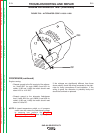
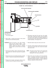
7. Bend the washer away from the rotor lock nut.
8. Using the 1-5/8” wrench to remove the nut from the
end of the armature shaft, then remove the washer
and sleeve collar.
NOTE: The sleeve collar will have to be removed with
a small gear puller. Be very careful not to
damage the rotor slip ring assembly.
9. Remove the rotor by pulling it off of the generator
shaft. If necessary, remove the screws and nuts
securing the lower front panel. This will allow the
panel to be shifted enough to provide the additional
clearance needed to remove the rotor.
TROUBLESHOOTING AND REPAIR
F-78 F-78
SAE-400 SEVERE DUTY
Return to Section TOC Return to Section TOC Return to Section TOC Return to Section TOC
Return to Master TOC Return to Master TOC Return to Master TOC Return to Master TOC