


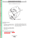


ALTERNATOR ROTOR REMOVAL AND REPLACEMENT (continued)
Rotor Replacement:
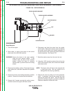
1. Clean and inspect the armature shaft, the exciter
rotor and slip rings. Replace the rotor if it is dam-
aged, or if the slip rings are excessively worn.
2. Carefully slide the rotor onto the armature shaft.
NOTE: It is recommended that a new sleeve collar,
washer and locking nut be used when installing
the exciter rotor.
3. Install the sleeve collar; if necessary, carefully tap
the collar into place. Be careful that the collar is not
damaged or deformed.
4. Install the washer, then the locking nut. Gently
tighten the nut and check that the rotor is fully seat-
ed and turning concentric on the shaft.
5. Torque the nut to 175 Ft-Lbs.
6. Bend the washer down to lock the nut in place.
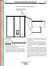
7. Check the rotor air gap. At the smallest point, the
gap should be wide enough to allow a .016 thick, ½”
wide feeler gage to pass between the rotor and sta-
tor.
8. Check the slip rings, brushes and brush holder
assembly. These parts must be clean and undam-
aged.
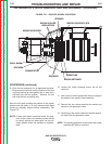
9. Mount the brush holder bracket assembly to the
exciter stator frame using the screws and nuts that
had been removed earlier. The brushes should ride
as close as possible to the center of each slip ring.
If necessary gently bend the brush holder bracket to
adjust the position.
10. Use a long strip is 180-grit sandpaper to seat the
exciter brushes. Place the sandpaper strip
between the slip rings and the brushes with the
abrasive side against the brushes. Pull the sand-
paper around the circumference of the slip rings in
the direction of rotation only. Repeat this proce-
dure until the brushes are contoured to match the
radius of the slip rings.
11. Attach the wires to the brush terminals. Proper
polarity is important
NOTE: On this machine, and all other Lincoln Electric
DC generator machines, the black exciter lead
is positive, and the red lead is negative.
12. If necessary, secure the lower front panel.
13. Install the exciter covers and batteries. Reconnect
the battery cables; connect the positive cables
first, followed by the negative cables.
14. Close the side doors if the work on the machine is
finished.
TROUBLESHOOTING AND REPAIR
F-79 F-79
SAE-400 SEVERE DUTY
Return to Section TOC Return to Section TOC Return to Section TOC Return to Section TOC
Return to Master TOC Return to Master TOC Return to Master TOC Return to Master TOC