


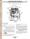
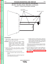
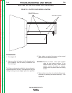
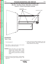

EXCITER COVER
FIVE SCREWS
(TWO ON OTHER SIDE)
FIGURE F.6 – EXCITER COVER SCREW LOCATIONS
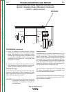
EXCITER ROTOR VOLTAGE TEST(continued)
PROCEDURE
1. Turn engine off.
2. Make sure that the battery is fully charged and in
good condition, and the battery connections are
clean and tight.
The Engine and generator should be at normal operat-
ing temperature for this test. If the machine is cold, the
voltage readings may be slightly higher than specified.
3. Open either, or both of the doors on the control
panel end of the SAE-400 machine.
WARNING: Secure the doors in the open position
using the door restraint system. If the
machine does not have a door restraint
system, remove the doors or securely
restrain them to prevent them from falling
closed.
4. Remove the covers from the exciter/auxiliary power
alternator by removing the screws securing it. See
Figure F.6.
TROUBLESHOOTING AND REPAIR
F-30 F-30
SAE-400 SEVERE DUTY
Return to Section TOC Return to Section TOC Return to Section TOC Return to Section TOC
Return to Master TOC Return to Master TOC Return to Master TOC Return to Master TOC