


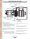

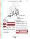
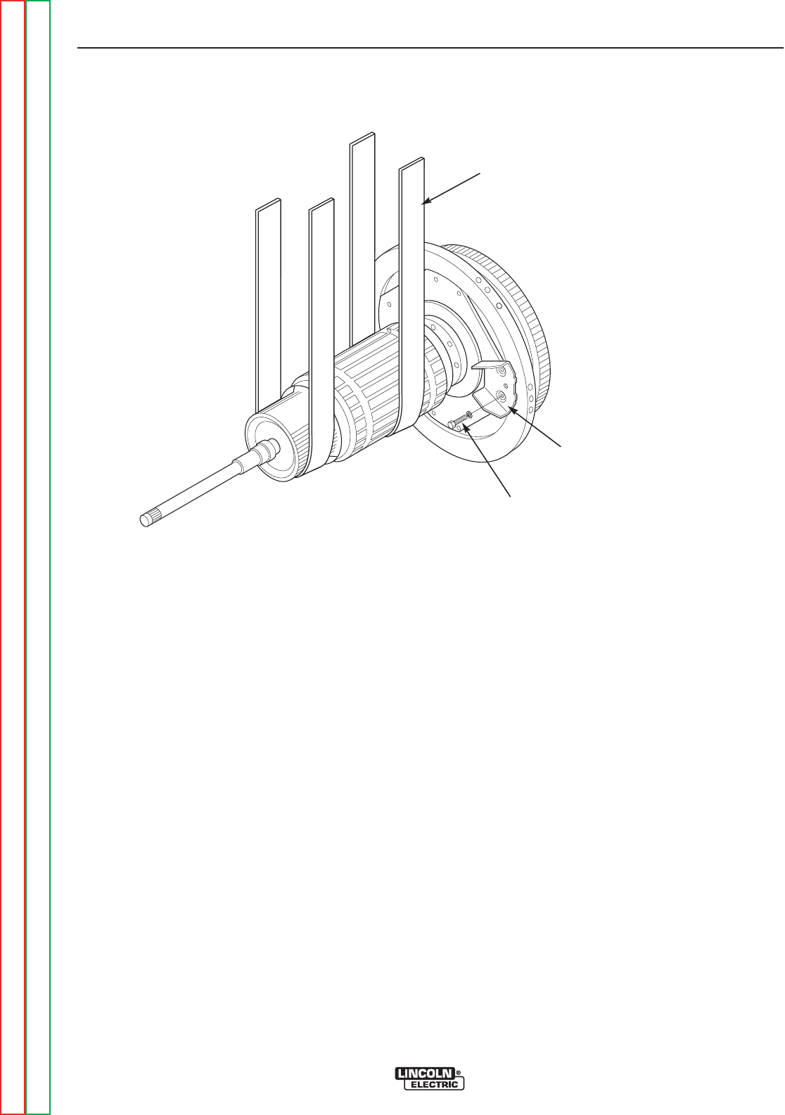
BLOWER
PADDLE/ARMATURE
MOUNTING BOLTS
(
8
)
BLOWER PADDLE
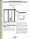
ROPE SLING
FIGURE F.32 – SLING LIFT
GENERATOR ARMATURE REMOVAL AND REPLACEMENT (continued)
PROCEDURE
Removing the Armature
1. Turn off the engine
2. Perform the Alternator Rotor Removal
Procedure.
3. Perform the Alternator Stator Removal
Procedure.
4. Perform the Generator Frame Removal
Procedure.
5. Using the rope sling, support the armature. Position
the sling at the center of gravity of the armature
assembly. See Figure F.32
6. Remove the eight screws securing the blower pad-
dle segments and the outer diameter of the flexible
coupling disk to the flywheel.
7. With the armature securely supported in the sling,
unlock it from the flywheel by carefully rotating it 1/8
of a turn in either direction.
Replacing the armature
1. Carefully inspect the mating surfaces of the fly-
wheel and armature coupling parts. These surfaces
must be clean and undamaged.
2. Support the armature in a rope sling and carefully
move it into position, and align it to the flywheel.
3. Rotate the armature 1/8 of a turn, in either direction,
to engage the locking mechanism and line up the
bolt holes. Be certain that the coupling plate is fully
and cleanly seated in the flywheel.
4. Replace the eight screws and four blower seg-
ments. Tighten the screws per the torque specifica-
tion sheet.
5. Perform the Generator Frame Replacement
Procedure.
6. Perform the Alternator Stator Replacement
Procedure.
7. Perform the Alternator Rotor Replacement
Procedure.
TROUBLESHOOTING AND REPAIR
F-88 F-88
SAE-400 SEVERE DUTY
Return to Section TOC Return to Section TOC Return to Section TOC Return to Section TOC
Return to Master TOC Return to Master TOC Return to Master TOC Return to Master TOC