


2 – General Description
Chassis LEDs
2-2 FI0154601-00 C
S
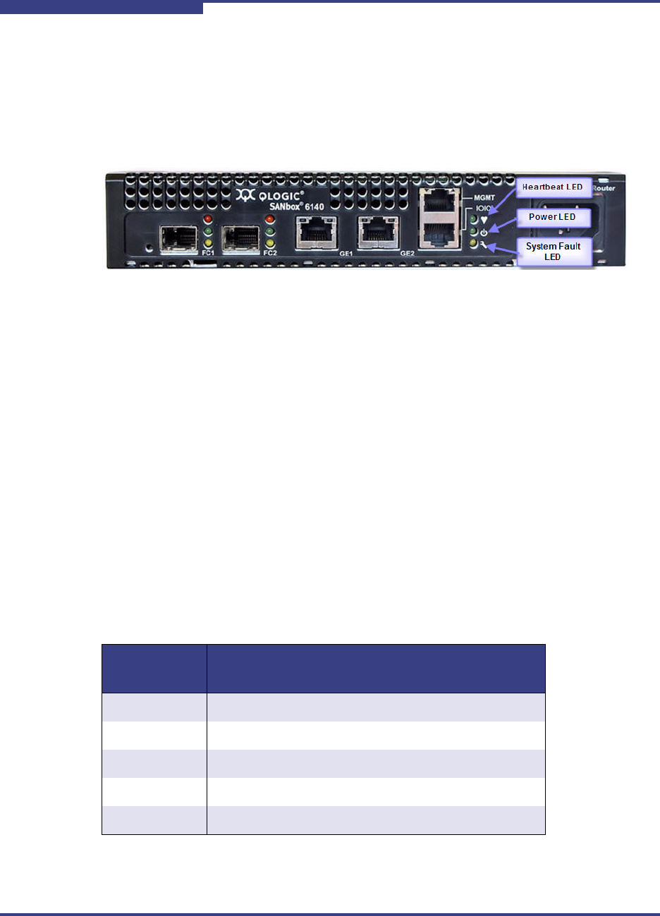
Chassis LEDs
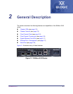
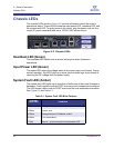
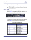
The chassis LEDs shown in Figure 2-2 provide information about the router’s
operational status. These LEDs include the input power LED, heartbeat LED, and
the system fault LED. To apply power to the router, plug the power cord into the
router AC power receptacle and into a 100-240 VAC power source.
Figure 2-2 Chassis LEDs
Heartbeat LED (Green)
The heartbeat LED blinks once a second as long the router firmware is
operational.
Input Power LED (Green)
The power LED shows the voltage status at the router logic circuit board. During
normal operation, this LED lights up to show that the router logic circuit board is
receiving the DC voltage from the power supply.
System Fault LED (Amber)
The system fault LED lights up to show that a fault exists in the router firmware or
hardware. Fault conditions include POST errors and over-temperature conditions.
The LED shows a blink code for POST errors and the over temperature condition.
See Figure 2-2 and Tabl e 2- 1.
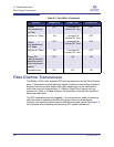
Table 2-1. System Fault LED Blink Patterns
System
Fault LED
Condition
OFF OK (operational)
3 Blinks System error
4 Blinks Management port IP address conflict
5 Blinks Over temperature
1 Blink Beacon - synchronized with the heartbeat LED