


Installation and Configuration 86
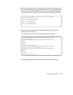
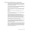
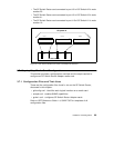
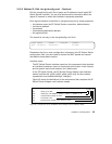
• The SP Switch Router card connected to port J31 of SP Switch A2 is node
number 25.
• The SP Switch Router card connected to port J31 of SP Switch A3 is node
number 41.
• The SP Switch Router card connected to port J15 of SP Switch A1 is node
number 16.
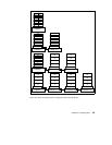
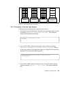
Figure 34. How Frames Enable Connections to Multiple SP Switches
3.7 Step-by-Step Media Card Configuration
This section provides a configuration overview and the steps required to
configure an SP Switch Router Adapter media card.
3.7.1 Configuration Files and Their Uses
These are the configuration files found in /etc on the SP Switch Router,
discussed in this chapter:
• grifconfig.conf - identifies each logical interface on a media card
• snmpd.conf - enables SNMP capabilities
• grdev1.conf - configures SP Switch Router Adapter cards
Refer to
GRF Reference Guide 1.4
, GA22-7367 for templates of all
configuration files.
Frame 1 Frame 3Frame 2
J7
J31 J15
J23
SP Switch A1
J7
J31 J15
J23
SP Switch A2
J7
J31 J15
J23
SP Switch A3
SP Switch Router
gt000
Node 9
gt030
Node 41
gt020
Node 25
gt010
Node 16
SP system A