


26 IBM 9077 SP Switch Router: Get Connected to the SP Switch
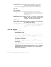
Power SupplyThe left side of the chassis is reserved for the two power
supplies that are required for redundancy.
The failed power supply can be hot-swapped out of the GRF chassis.
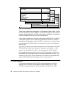
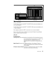
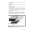
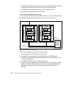
GRF 1600
Part Description
Cooling FansThese are located at the top of the chassis, and can be
accessed separately from the other parts of the
GRF. The fan tray contains redundant fans and is
hot-swappable.
Media CardsThere are 16 media card slots on this chassis. They are slotted
vertically. Eight of the cards are on the left side of
the chassis, and eight are on the right side.
IP Switch and
Control BoardThese boards are located in the middle of the 16 media slots
and are also slotted vertically.
Power SupplyThe base of the chassis is reserved for the two power supplies
that are required for redundancy. The failed power
supply can be hot-swapped out of the GRF
chassis.
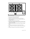
2.3.2 GRF Features
GRF has the following features:
• Redundant power supply
Should any power supply fail, a message is sent to the control board. The
power supply will automatically reduce its output voltage if the
temperature exceeds 90 °C (194 °F). If the voltage falls below 180V, the
GRF automatically shuts down.
• Hot-swappable power supply
The faulty power supply can be replaced while the GRF is in operation.
• Redundant fan
For the GRF 1600 model, if one fan breaks down, a message is sent to the
control board.
For both models, when the temperature reaches 53°C (128 °F), an audible
alarm sounds continuously, and a message is sent to the console and
logged into the message log.