


174 IBM 9077 SP Switch Router: Get Connected to the SP Switch
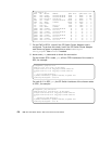
An ATM adapter establishes a duplex connection to its partner, so the 16.5
MB/s write throughput should be accompanied by another 16.5 MB/s read
throughput. To prove this, we started two ftp put commands from the same
SP21 node. At the same time we started two ftp put commands an the F50
and observed an aggregate throughput over the ATM adapter of up to 28
MB/s, with the CPU of the SP node nearly 80% busy and the F50 100%
busy.
5.1.4 SP Switch - FDDI Connection (Distinct FDDI Networks)
5.1.4.1 SP Switch - FDDI Connection without Bridging
This scenario is rather similar to the one described in Section 5.1.2, “SP
Switch - FDDI Connection” on page 162 and is quite often met in customer
environments. It might be used to connect four different FDDI backbones to a
SP Switch, for instance in an ADSM environment.
Configuration assumptions:
• An SP Switch Router FDDI media card has been installed according to
Section 4.4, “FDDI Configuration” on page 121 and works properly.
• An SP Switch Router Adapter card has been installed according to Section
3.7, “Step-by-Step Media Card Configuration” on page 86 and works
properly.
• The SP Switch Router Adapter card and SP processor node Switch
adapters are in the same IP subnet.
• ARP should be enabled on the SP Switch network to provide the most
flexibility in assigning IP Addresses (strongly recommended!).
• If ARP is disabled on the SP Switch network, the IP addresses assigned to
the nodes must be determined by the Switch node numbers. Refer to
PSSP Planning, Volume 2, Control Workstation and Software Environment
for details.
Note:
The SP Switch Router Adapter card will not properly forward IP data to
nodes assigned with an IP address that is in another subnet.
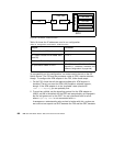
Configuration:
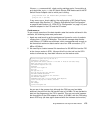
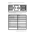
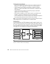
To establish this scenario, the FDDI interfaces of node 9, node 10, node 11
and node 12 in SP2 were connected to the SP Switch Router FDDI media
card’s port B1, port A1, port B0 and port A0, respectively. (This "weird"
connection had to be chosen because of limited cable length in our lab
environment . Any other cabling might be used.). The SP Switch Router
Adapter card is attached to the SP Switch of SP21, as shown in Figure 56 on