


© Copyright IBM Corp. 1998 67
Part 2. Scenarios
This part presents some sample configurations of an RS/6000 SP system
with an SP Switch Router. It is beyond the scope of this book to represent all
possible applications of an SP Switch Router. Nevertheless, the basic
configurations shown are building blocks for more complex networking
topologies that include the SP Switch Router and may inspire more complex
configurations.
All following sample scenarios were carefully chosen to match frequently
occurring customer situations. They can be easily configured and modified to
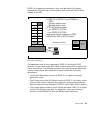
apply to customers’ needs. All configurations described were tested in our
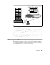
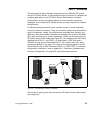
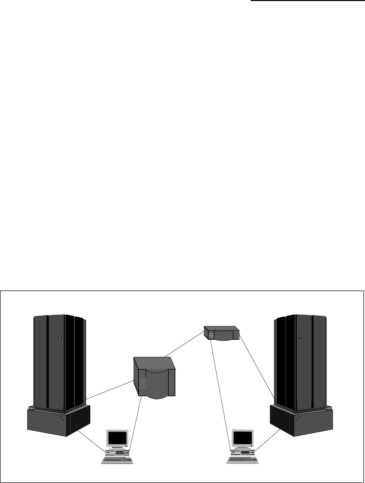
laboratory with the available hardware and software. We used two RS/6000
SPs, each consisting of a control workstation (CWS) and one frame with an
SP Switch and several nodes (see Figure 27). All nodes and the CWS were
installed with AIX 4.3.1 and PSSP 2.4. Additionally, a GRF1600 and a
GRF400 running Ascend Embedded/OS V1.4.6.4. were used. Only static
routing was applied in our tests. For using and configuring gated on an SP
Switch Router refer to
GRF Reference Guide 1.4,
GA22-7367. For detailed
configuration information, refer to Appendix A, “Laboratory Hardware and
Software Configuration” on page 233, and the scenario sections.
Figure 27. The Laboratory Hardware Installation
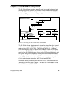
But first let us get physical and see how the SP Switch Router media cards
are configured.
SP 21 SP 2
GRF 400
GRF 1600
CWS 21
CWS 2