


206 IBM 9077 SP Switch Router: Get Connected to the SP Switch
cards shows up green in perspectives or enter SDRGetObjects
switch_responds
. Use Eunfence if needed.
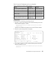
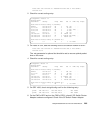
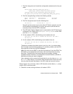
7. Issue some
ping commands to check the connection:
On the SP2 nodes,
ping the SP Switch interface of any node in SP21:
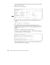
On the SP21 nodes,
ping the SP Switch interface of any node in SP2:
If these
ping commands fail, check routing settings again. If everything is
as it should be, try to
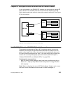
ping both SP Switch Adapter cards to find the failing
part:
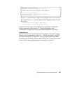
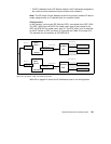
ping 192.168.13.16 (on SP2 nodes)
ping 192.168.14.4 (on SP21 nodes)
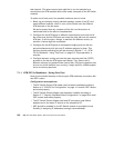
If any errors occur, check cabling, the configuration of the SP Switch
Router cards (see Section 3.7, “Step-by-Step Media Card Configuration”
on page 86) and also the switch adapters in the nodes.
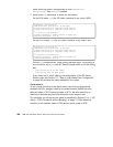
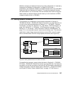
Performance:
To get a rough overview of the data transfer rates that can be achieved
between the SPs, we again used ftp to transfer several 300MB files from
different nodes in SP2 to several nodes in SP21. We sent these files to
/dev/null to eliminate any hard disk influence on the receiver side.
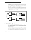
The requisites for this test are the same as described in Section 5.1.4.1, “SP
Switch - FDDI Connection without Bridging” on page 174. We started ftp
transfers on all available nodes of SP2 and on some nodes of SP21.
root@sp2n01:/ ping 192.168.14.1
PING 192.168.14.1: (192.168.14.1): 56 data bytes
64 bytes from 192.168.14.1: icmp_seq=0 ttl=254 time=1 ms
64 bytes from 192.168.14.1: icmp_seq=1 ttl=254 time=1 ms
^C
----192.168.14.1 PING Statistics----
2 packets transmitted, 2 packets received, 0% packet loss
round-trip min/avg/max = 1/1/1 ms
root@sp21n01:/ ping 192.168.13.1
PING 192.168.13.1: (192.168.13.1): 56 data bytes
64 bytes from 192.168.13.1: icmp_seq=0 ttl=254 time=1 ms
64 bytes from 192.168.13.1: icmp_seq=1 ttl=254 time=1 ms
^C
----192.168.13.1 PING Statistics----
2 packets transmitted, 2 packets received, 0% packet loss
round-trip min/avg/max = 1/1/1 ms