


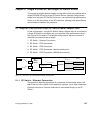

Single RS/6000 SP and Single SP Switch Router 165
6. On the CWS of SP2 check if the SP Switch Router Adapter card is
configured. See if the SP Switch Router Adapter card shows up green in
perspectives or enter
SDRGetObjects switch_responds. Use Eunfence if
needed.
7. Issue some
ping commands to check the connection:
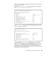
On the chosen SP2 nodes,
ping the FDDI interface of node 10 in SP21, for
example:
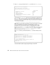
On node 10 in SP21,
ping the SP Switch interfaces of the chosen nodes in
SP2, for example:
If these
ping commands fail, check routing settings again. If everything is
as it should be, try to
ping the SP Switch Router FDDI media card or the
SP Switch Router Adapter card to ascertain the failing part:
ping 192.168.13.4 (on chosen processor nodes in SP2)
ping 10.2.1.2 (on node 10 in SP21)
If any errors occur, check cabling, the configuration of the SP Switch
Router media cards (See Section 3.7, “Step-by-Step Media Card
Configuration” on page 86 and Section 4.4, “FDDI Configuration” on page
121) and also the network adapters in the nodes.
Performance:
To get a rough overview of the data transfer rates that can be achieved in
such a scenario, we performed the following tests:
1. We obtained of tsock program (a derivative of the public domain ttcp
program developed by T.C. Slattery, USNA, improved by Mike Muuss,
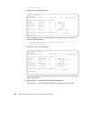
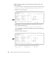
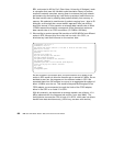
root@sp2n09:/ ping 10.2.1.1
PING 10.2.1.1: (10.2.1.1): 56 data bytes
64 bytes from 10.2.1.1: icmp_seq=0 ttl=255 time=0 ms
64 bytes from 10.2.1.1: icmp_seq=1 ttl=255 time=0 ms
^C
----10.2.1.1 PING Statistics----
2 packets transmitted, 2 packets received, 0% packet loss
round-trip min/avg/max = 0/0/0 ms
root@sp21n10:/ ping 192.168.13.9
PING 192.168.13.9: (192.168.13.9): 56 data bytes
64 bytes from 192.168.13.9: icmp_seq=0 ttl=255 time=0 ms
64 bytes from 192.168.13.9: icmp_seq=1 ttl=255 time=0 ms
^C
----192.168.13.9 PING Statistics----
2 packets transmitted, 2 packets received, 0% packet loss
round-trip min/avg/max = 0/0/0 ms