


128 IBM 9077 SP Switch Router: Get Connected to the SP Switch
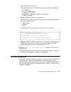
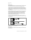
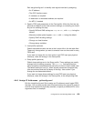
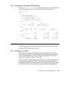
Figure 47. Physical Interface Numbering on the FDDI Media Card
The diagram shows physical interface numbering to be 0-based (0–3),
whereas SNMP numbering is 1-based (1–4).
4.4.4 GRF Interface Name
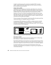
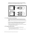
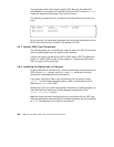
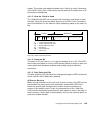
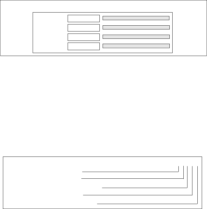
The GRF interface name has five components that describe an individual
FDDI interface in terms of its place on the media card and in the GRF router.
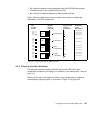
Follow the naming conventions shown in Figure 48 and keep in mind that all
interface names are case sensitive and that you must use all lowercase.
Figure 48. GRF Interface Name for FDDI Interfaces
The interface name and IP address are specified in the /etc/grifconfig.conf
file.
4.4.5 Configuration Files and Profiles
Following are the steps to configure FDDI cards. They are listed here
complete, although you can bring up an FDDI connection with a subset. For
detailed information, see
GRF Configuration Guide 1.4,
GA22-7366.
Proceed as follows:
1. Identify each logical interface.
01
34
23
12
Port
SNMP
A0
B1
B0
A1
FDDI
media
card
2nd: media type, f (FDDI)
1st: always "g" for GRF
3rd: chassis number, always "0" (zero)
4th: slot number in hex
5th: logical interface number in hex
g f 0 x y