


Installation and Configuration 80
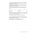
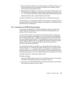
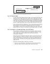
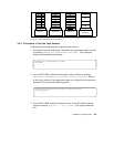
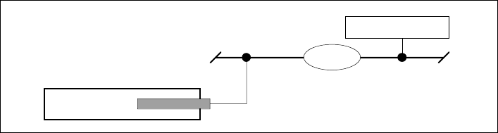
Figure 31. SP System Administrative Ethernet Connections
3.4.2 SP Switch Cable
The SP Switch Router Adapter card provides one full-duplex attachment and
requires a specific cable with 50-pin connector ends, obtainable from IBM.
The cable has a unique signal wiring map, and is not replaceable by a 50-pin
HSSI cable, for example. SP Switch Router Adapter card cables are available
in 10- and 20-meter lengths (32 or 65 feet). Excess cable lengths should be
bound in a figure-eight pattern. Do not wind excess cable into circular coils.
Each connector end has 50 fragile pins. Pins can become bent when making
the connection to the media card if alignment is wrong. If an SP Switch
Router Adapter card link does not work after cabling, check both ends of the
cable for bent pins. When not connected, keep the plastic caps on the ends.
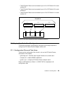
3.4.3 Procedure for Connecting Cards to the SP Switch
This procedure connects the SP Switch Router Adapter card(s) to the SP
Switch. Before the SP Switch Router unit can begin full operation, all other
router media cards must be configured with appropriate customer
configuration information.
Make sure you have labeled the SP Switch cable to show which media card
and SP Switch port it will be connected to. Keep in mind that for any work
done on the SP Switch you should have shut down and powered off the SP
System and also turned off the central power supply switch at the left front
edge of the SP.
Execute the following steps to make the connections:
1. If there are any terminators on the media card or the switch assembly
where you need to attach the switch cable, remove them now.
SP Control Workstation
Hub
Administrative Ethernet network
SP Switch Router
Control board