


Installation and Configuration 75
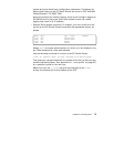
4. Methods to determine node number and SP Switch port for an SP Switch
Router Adapter card
5. A step-by-step configuration of an SP Switch Router Adapter card
6. A list of ways to verify that the SP Switch Router Adapter card is correctly
installed in the SP Switch Router
7. A description of what needs to occur to bring the card online to the SP
system
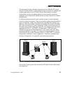
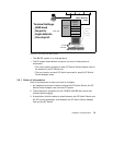
3.3 Installing an SP Switch Router Adapter Card
This section contains the procedure for physical installation and minimal
configuration of the SP Switch Router Adapter card for use as an SP
dependent node. This includes cabling the GRF to the SP CWS and the
appropriate SP Switch port.
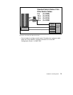
Note
: There needs to be a network path between Ethernet twisted-pair
interface on the SP Switch Router control board and the SP control
workstation. This is most easily done through an Ethernet hub (or bridge to
the 10BaseT SP LAN). However, it can also be done through a connection to
a network external to the SP.
3.3.1 Installation Overview
IBM support personnel who install the SP Switch Router (9077) perform the
physical installation and minimal configuration described below with help from
the customer’s system administrator. The system administrator must
complete the following basic configuration steps:
1. Locate all the components of the SP Switch Router chip group.
2. Perform the complete physical installation of the SP Switch Router unit as
described in the "Power On and Initial Configuration" chapter of
GRF 400/
1600 Getting Started 1.4,
GA22-7368. Make sure that when the "First-time
power on configuration script" runs at system boot, the required
configuration information is provided by or entered by the customer. This
information includes the SP Switch Router unit IP address and hostname.
As stated before, ignore script references to network or syslog logging.
3. Perform the procedure to configure the PCMCIA disk. The procedure is
included in Section 3.3.2, “Installing the PCMCIA Spinning Disk” on page
76.