


Single RS/6000 SP and Single SP Switch Router 185
vice versa. We sent these files to /dev/null to eliminate any hard disk
influence on the receiver side.
The hardware requisites for this test are the same as described in Section
5.1.4.1, “SP Switch - FDDI Connection without Bridging” on page 174. The
slow internal SCSI disks in two of our four nodes in SP2 would not allow the
transfer rate to exceed 4.5 MB/s. Both remaining nodes in SP2 contain faster
SSA hard disks that allow a transfer rate of 7.5 MB/s. Nevertheless, the
overall achievable data transfer rate will not exceed the bandwidth of the
FDDI connection. So we decided to start several ftp programs on nodes in
SP2 and SP21 to sum up the transfer rates.
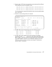
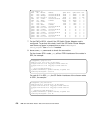
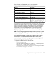
With this scenario, we again measured a cumulative transfer rate of up to 44
MB/s (observed with the freeware tool monitor) that is close to the maximum
theoretical transfer rate of 4x12.5 MB/s=50 MB/s. Every node’s FDDI
interface contributed an overall transfer rate of about 11 MB/s (sending and
receiving). The limiting factor once again was the CPU on the four nodes in
SP2 that was not able to handle more data simultaneously (100% busy, as
seen with monitor). We could not find any significant influence of bridging on
the measured data transfer rate.
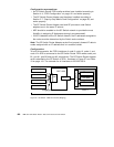
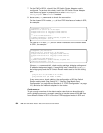
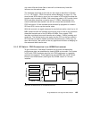
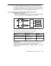
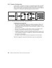
5.1.5 SP Switch - FDDI Connection in an ADSM Environment
To get a view into a "real world" scenario and to check corresponding
performance data, we established a simple ADSM environment. Four nodes
in SP2 with FDDI interfaces stand for four FDDI backbones in a possible
customer environment. These backbones send ADSM data via SP Switch
Router to an ADSM server (see Figure 58). ADSM version 3.1.20 was
installed.
Figure 58. SP Switch Router in an ADSM Environment
node 11
SP Switch
GRF 1600
FDDI
A0
B1
B0
A1
SP21
node 12
node 10
node 9
bridge group
ADSM server
SP2
ADSM clients
SP Switch Router
Adapter card 1
node 1