


Router Node 29
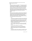
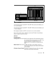
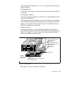
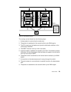
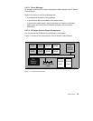
Figure 13. Data Packet Transfer
The routing can be divided into the following steps:
1. A data packet is received by the media card.
2. The packet is transferred to the receive buffer by the DMA engine.
3. The CPU examines the header and gives the destination address to the
route lookup hardware.
4. The QBRT finds the next hop in the route table.
5. A special header is added to the packet by the CPU. This header contains
information for the downstream card to process the packet, as well as the
next hop found by the QBRT.
6. The packet is then transferred to the internal serial interface by the DMA
engine.
7. A connection to the downstream card is set up through the switch.
8. The serial stream is converted back to parallel format by the downstream
card.
9. The packet is transferred to the transmit buffer by the DMA engine.
Tx Buffer
Rx Buffer
CPU
QBRT
DMA
DMA
Internal
Interface
External
Interface
Tx Buffer
Rx Buffer
CPU
QBRT
DMA
DMA
Internal
Interface
External
Interface
Switch
Control Board
Dynamic
Route
Manager