


180 IBM 9077 SP Switch Router: Get Connected to the SP Switch
Configuration assumptions:
• An SP Switch Router FDDI media card has been installed according to
Section 4.4, “FDDI Configuration” on page 121 and works properly.
• The SP Switch Router Adapter card has been installed according to
Section 3.7, “Step-by-Step Media Card Configuration” on page 86, and
works properly.
• The SP Switch Router Adapter card and SP processor node Switch
adapters are in the same IP subnet.
• ARP should be enabled on the SP Switch network to provide the most
flexibility in assigning IP Addresses (strongly recommended!).
• If ARP is disabled on the SP Switch network, the IP addresses assigned to
the nodes must be determined by the Switch node numbers.
Note:
The SP Switch Router Adapter card will not properly forward IP data to
nodes assigned with an IP address that is in another subnet.
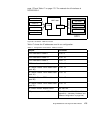
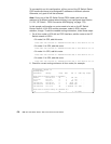
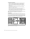
Configuration:
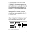
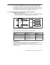
To build this scenario, the FDDI interfaces of node 9, node 10, node 11 and
node 12 in SP2 is connected to the SP Switch Router FDDI media card’s port
B1, port A1, port B0 and port A0, respectively. The SP Switch Router Adapter
card is attached to the SP Switch of SP21, as shown in Figure 57 and Table
18 on page 181. The netmask for all interfaces is 255.255.255.0.
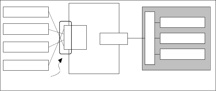
Figure 57. SP Switch - FDDI Connection (Bridging)
node 11
SP node
SP Switch
GRF 1600
SP node
FDDI
A0
B1
B0
A1
SP21
node 12
node 10
node 9
bridge group
SP Switch Router
Adapter card 1
SP node