


© Copyright IBM Corp. 1998 295
Appendix C. Hardware and Software Information
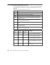
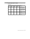
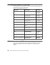
Appendix C gives an overview of the LEDs on the front panel of the SP
Switch Adapter card and shows tables with the meaning of the LEDs’ blinking
patterns.
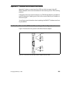
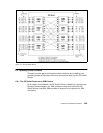
A diagram of the chip interconnections on a TBS Switch Board is provided for
a quick reference in helping you to find out the correct Switch port numbers or
the correct jack.
You will get some information about updating the IBM 9077 software and how
to get updates.
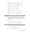
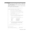
C.1 The Front Panel of the SP Switch Router Adapter Card - Operational
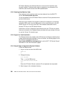
Figure 72 shows the front panel of the Switch Router adapter:
.
Figure 72. Front Panel of the SP Switch Router Adapter Card with LEDs
PWR ON
3V
RX HB
RX ST0
RX ST1
RX ERR
MD RCV
SW XMIT
TX HB
TX ST0
TX ST1
TX ERR
MD XMIT
SW RCV