


Multiple RS/6000 SPs and Multiple GRFs 223
Configuration assumptions:
• The SP Switch Router ATM media card has been installed according to
Section 4.3, “ATM OC-12c Configuration” on page 119 on both GRF
routers and works properly.
• The SP Switch Router Adapter card has been installed according to
Section 3.7, “Step-by-Step Media Card Configuration” on page 86 on both
GRF routers and works properly.
• The SP Switch Router Adapter card and SP processor node Switch
adapters are in the same IP subnet on the respective SP.
• ARP should be enabled on the SP Switch network to provide the most
flexibility in assigning IP addresses (strongly recommended!).
• If ARP is disabled on the SP Switch network, the IP addresses assigned to
the nodes must be determined by the switch node numbers.
Note:
The SP Switch Router Adapter card will not properly forward IP data to
nodes assigned with an IP address that is in another subnet.
Configuration:
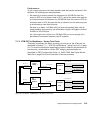
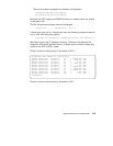
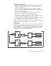
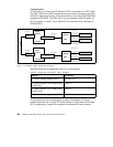
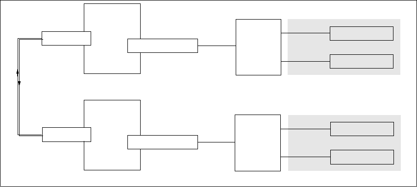
In this scenario, we have the SP Switch of SP21 connected to the GRF 1600.
The GRF 1600 has its ATM OC-12c media card’s port 00 connected to the
GRF 400 ATM OC-12c media card’s port 00. The GRF 400 in turn is attached
to the SP Switch of SP2, as shown in Figure 70 and Table 25 on page 224.
The netmask on all interfaces is 255.255.255.0.
Figure 70. SP Switch - ATM OC-12c - SP Switch Connection
Mask 255.255.255.0
SP
Switch
Router 1
GRF 400
SP Switch Router
Adapter card 1
SP Switch 1
SP2
SP processor node
SP processor node
IP 192.168.13.4
Mask 255.255.255.0
Mask 255.255.255.0
Net 192.168.13.0
SP
Switch
Router 2
GRF 1600
SP Switch Router
Adapter card 2
SP Switch 2
SP21
SP processor node
SP processor node
IP 192.168.14.4
Mask 255.255.255.0
Net 192.168.14.0
ATM OC-12c
Adapter card
ATM OC-12c
Adapter card
Net 10.50.1.2
Net 10.50.1.1