


Single RS/6000 SP and Single SP Switch Router 195
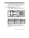
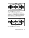
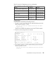
Figure 61. IP Traffic Flow When Issuing ping 192.168.13.1 on Node 6
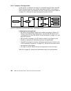
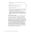
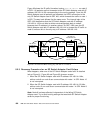
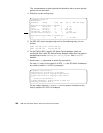
Figure 63 on page 196 shows the IP traffic flow when issuing the ping
192.168.13.1
on node 10 in SP21. All packets are first forwarded to the SP
Switch Adapter card with IP address 192.168.14.129 corresponding to the
routing settings. From this SP Switch Adapter card all packets are forwarded
via HIPPI connection to the only SP Switch Adapter card in GRF 400, which
forwards the traffic to node 1 in SP2. The way back follows the same route.
The SP Switch Adapter card with IP address 192.168.14.129 has no problem
delivering IP packets to node 10 that is in the same subnet.
Figure 62. IP Traffic Flow When Issuing ping 192.168.13.1 on Node 10
192.168.13.1
255.255.255.0
192.168.14.129
255.255.255.128
node 1 node 6
SP Switch
Adapter
SP Switch
Adapter
SP Switch
Adapter
HIPPI
HIPPI
GRF 400 GRF 1600
SP Switch
SP Switch
192.168.14.4
255.255.255.128
192.168.14.6
255.255.255.0
192.168.13.1
255.255.255.0
192.168.14.129
255.255.255.128
node 1
node 10
SP Switch
Adapter
SP Switch
Adapter
SP Switch
Adapter
HIPPI
HIPPI
GRF 400 GRF 1600
SP Switch
SP Switch
192.168.14.4
255.255.255.128
192.168.14.130
255.255.255.0