


Installation and Configuration 74
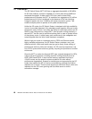
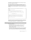
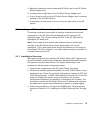
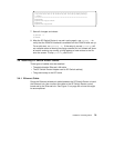
Figure 30. Connecting the GRF Console
• The IBM SP system is up and operating.
• The SP system administrator has given you one of these pieces of
information:
• The node number assigned to each SP Switch Router Adapter card to
be attached to an SP Switch port
• The port location on each SP Switch reserved for specific SP Switch
Router Adapter cards
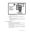
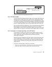
3.2.1 Order of Information
Here is the sequence of steps you have to complete:
1. An installation overview of tasks involving the SP Switch Router, the SP
Switch Router Adapter card, and the SP system
2. The configuration procedure for the PCMCIA 520 MB disk, which also
initiates system logging
3. A description of which cables to attach between the SP Switch Router and
the SP control workstation, and between the SP Switch Router Adapter
card and the SP Switch
Terminal Settings
9600 baud
No parity
Eight data bits
One stop bit
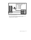
GRF 400
VT100
terminal
GRF Console (optional)
RS232
(Null
Modem
Cable)
Admin Ethernet
(de0)
cws
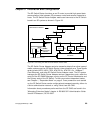
Crosspoint
Switch
IP Switch
Control
Board
SP Switch