


176 IBM 9077 SP Switch Router: Get Connected to the SP Switch
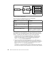
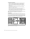
To successfully run this configuration, all four ports of the SP Switch Router
FDDI media card have to be assigned IP addresses in different subnets.
Otherwise, only port A0 will be activated.
Note:
Every port of the SP Switch Router FDDI media card has to be
assigned to a different subnet when bridging is not configured (see Section
5.1.4.2, “SP Switch - FDDI Connection with Bridging” on page 179).
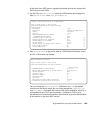
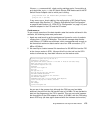
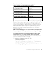
In this sample configuration no routes need to be set on the SP Switch
Router. Node 9-12 on SP2 and the processor nodes in SP21 require
attention, though. To add the needed routing information, follow these steps:
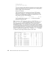
1. On all four nodes in SP2 with an FDDI interface, add the route to the SP
Switch network of SP21:
• On node 9 in SP2, add this route:
route add -net 192.168.14 -netmask 255.255.255.0 -mtu 4352 10.5.1.18
• On node 10 in SP2, add this route:
route add -net 192.168.14 -netmask 255.255.255.0 -mtu 4352 10.3.1.16
• On node 11in SP2, add this route:
route add -net 192.168.14 -netmask 255.255.255.0 -mtu 4352 10.4.1.17
• On node 12 in SP2, add this route:
route add -net 192.168.14 -netmask 255.255.255.0 -mtu 4352 10.2.1.15
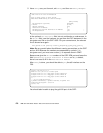
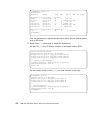
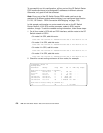
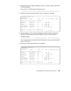
2. Check for correct routing entries on all four nodes, for example:
root@sp2n09:/ netstat -rn
Routing tables
Destination Gateway Flags Refs Use If PMTU Exp Groups
Route Tree for Protocol Family 2 (Internet):
default 192.168.3.37 UG 0 390 en0 - -
10.5.1/24 10.5.1.9 U 1 2 fi0 - -
127/8 127.0.0.1 U 8 906 lo0 - -
192.168.3/24 192.168.3.9 U 9 85376 en0 - -
192.168.13/24 192.168.13.9 U 2 731853 css0 - -
192.168.14/24 10.5.1.18 UG 0 10460318 fi0 4352 -
Route Tree for Protocol Family 24 (Internet v6):
::1 ::1 UH 0 0 lo0 16896 -