


Single RS/6000 SP and Single SP Switch Router 163
• If ARP is disabled on the SP Switch network, the IP addresses assigned to
the nodes must be determined by the Switch node numbers. Refer to
PSSP Planning, Volume 2, Control Workstation and Software Environment
for details.
Note:
The SP Switch Router Adapter card will not properly forward IP data to
nodes assigned with an IP address that is in another subnet.
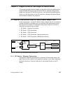
Configuration:
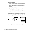
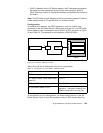
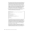
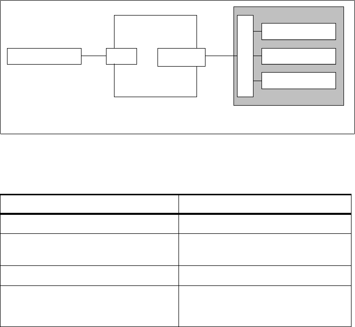
To establish this scenario, the FDDI interface of node 10 in SP21 was
connected to the SP Switch Router FDDI media card, port A0. The SP Switch
Router Adapter card is attached to the SP Switch of SP2, as shown in Figure
54 and Table 15. The netmask for all interfaces is 255.255.255.0.
Figure 54. SP Switch - FDDI Connection
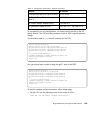
Table 15 shows the IP addresses used in our configuration.
Table 15. Configuration of an SP Switch - FDDI Connection
To successfully run this configuration, no routes need to be set on the SP
Switch Router. Node 10 and the processor nodes in SP2 require attention,
Adapter IP Address
FDDI interface in node 10 10.2.1.1
SP Switch Router FDDI media card
(port A0)
10.2.1.2
SP Switch Router Adapter card 1 192.168.13.4
SP processor nodes in SP2
192.168.13.1 - 192.168.13.15
(See
Appendix A, “Laboratory Hardware and
Software Configuration” on page 233.)
node10
SP node
SP Switch
GRF 400
SP node
FDDI
A0
SP2
SP Switch Router
Adapter card 1
SP node