


282 IBM 9077 SP Switch Router: Get Connected to the SP Switch
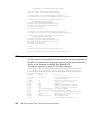
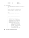
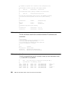
2.21.16.1.1.12 2 # Node State
2.21.16.1.1.13 0 # Switch Chip Link
2.21.16.1.1.14 64 # Node Delay (cycles)
2.21.16.1.1.15 1 # Admin Status
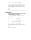
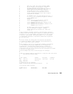
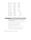
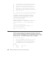
B.10 /etc/grifconfig.conf
This file documents the correlation of the logical interfaces on the media
cards in the GRF to IP addresses, together with some other information, like
MTU.
# NetStar $Id: grifconfig.conf,v 1.10.2.3 1997/08/01 17:24:04 pargal Exp $
#
# Configuration file for GigaRouter/GRF interfaces.
#
# The contents of this file specify the IP addressing information for
# the networks attached to the system’s interfaces. This includes
# interfaces on media cards as well as directly attached interfaces
# such as de0 or ef0 (maintenance Ethernet) or lo0 (software loopback).
#
# The addresses of directly attached interfaces are configured
# directly from this file by the /etc/netstart calling the grifconfig(8)
# script.
#
# The addresses of the interface(s) on a given media card are
# configured into the BSD/OS kernel when the media card boots and
# comes on line.
#
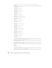
# Each entry in this file has the following format:
#
# name address netmask broad_dest arguments
#
# The name of a GigaRouter interface encodes the hardware type,
# GigaRouter cage number, slot number, and interface number.
#
# -- The first character must be ’g’ (to specify a GigaRouter
# interface).
# -- The second character is the hardware type of the
# interface: ’a’ for ATM, ’e’ for ETHERNET,
# ’f’ for FDDI, ’h’ for HIPPI, ’p’ for PPP, ’s’ for HSSI.
# (’l’ is also used, for GigaRouter software loopback.)
# -- The third character is the number of the GigaRouter cage.
# (Currently this must be ’0’, as multiple GigaRouter cages
# are not yet supported.)
# -- The fourth character is the hex digit (0 through f) of
# the slot number within the GigaRouter cage.
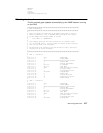
# -- The fifth (and sixth) characters specify the number of the
# LOGICAL interface on the card:
#
# For ATM cards, the fifth and sixth characters are
# the hex digits of the logical interface. Logical
# interfaces numbered from 0 to 7f are on the top
# physical connector on the ATM card, and logical
# interfaces numbered 80 to ff are on the bottom
# physical connector. NOTE: These logical interface
# numbers are NOT the same as the VPI/VCI numbers
# of a PVC (see /etc/grpvc.conf for that).
#
# For FDDI cards, the fifth character will be 0, 1,
# 2, or 3 to specify the logical interface on the