


Installation and Configuration 81
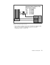
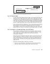
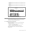
2. Using appropriate frame entry and exit holes for cable management, route
the SP Switch cable between the SP Switch Router unit and the SP
Switch.
3. Connect the SP Switch cable to both the media card and the correct SP
Switch port, as follows:
• Connection to media card
The EMI shielding fitted inside the connector end can make insertion
difficult, so be sure to insert the connector end as perpendicular as
possible. (Pins can be damaged when the connector is inserted at too
much of an angle.) Seat the connector firmly so the spring clips engage.
• Connection to SP Switch port
The cable ends should click onto the connectors. Determining the correct
Switch port is described in Section 3.5.1, “Determining the Switch
Connection for a Dependent Node” on page 82.
4. Make sure both ends of the cable are firmly seated by pulling on them
lightly.
At this point, the SP Switch Router Adapter card configuration information
must be entered on the SP CWS to enable the PSSP code and SP Switch to
recognize the adapter. These tasks are discussed in Section 3.5,
“Configuration Required on the SP System” on page 81.
3.5 Configuration Required on the SP System
This section describes the SP Switch Router-related configuration
information that should be defined by the SP administrator and then entered
from the SP CWS before the SP Switch Router Adapter card is configured.
The SP Switch Router-related configuration information includes the
following:
• The SP Switch Router Ethernet IP address
• The SP Switch Router Ethernet hostname (that is, the SP Switch Router’s
administrative Ethernet hostname)
• Unique node numbers for SP Switch Router Adapter cards
The SP Switch Router Adapter card configuration information enables the
PSSP code and the SP Switch to recognize and communicate with this card.